• HTML tutorial

Road

Not into ranks, titles or points.
Launch Member

Advocate III

3,379
On the road in North America
First Name
Road
Last Name
Dude
Member #

6589

Quite the contrary! You have been very helpful, and the linked articles were chock full of great information.
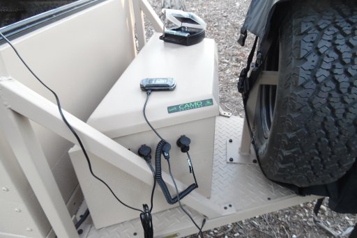
I will not be using the truck's 7-pin connector to charge the trailer's battery. I'm keeping them completely separated. I do plan to run a power cable from the trailer battery directly to the fridge/freezer in the truck when parked for an extended time, so that I'm using the trailer's Odyssey battery rather than the truck's starting battery.

Thank you again for steering me in the right direction!
Look into Andersen connectors for the hookup from trailer to truck, if you haven't already. Makes it so much easier. Also, most fridge/freezers have built-in battery protection that sense low battery level and cut back on power consumption. I kept thinking, with my ARB 50, that I needed to plug it into my trailer battery instead of my van battery when parked, or turn it off overnight, but it's proven to be so effective at both low power consumption (once down to temp) and sensing my van battery level that it hasn't been a problem. I'm going to test it further in hotter weather when the fridge will be cycling more.

Glad you're getting it figured out! I love learning this stuff.
 
  • Like
Reactions: Steve

Steve

lost again...
Founder 500
Launch Member

Traveler III

4,312
Lorain County, OH, USA
First Name
Steve
Last Name
None
Member #

202

Also, most fridge/freezers have built-in battery protection that sense low battery level and cut back on power consumption.
Yep, my National Luna 90 Twin has three shutoff level settings. I've kept it on the highest (safest) setting for up to 48 hours in cold weather, and 36 hours in hot without it kicking in. I've not had to go longer, so I don't know when it would actually shut down. That's with both sides at 37°F, not with the freezer side at 0°F. Still, I'd rather cycle the deep cycle battery than the starting battery.

I currently have a mix of SAE and Powerlet plugs and receptacles on my various 12V devices. The Powerlet is what came on my fridge, so I added an outlet in the back and in the grill of the trucker convenience. I'll likely convert over to Anderson connectors at some point.
 
  • Like
Reactions: Road

nickburt

Rank VII
Launch Member

Creator III

5,613
Wallasey, Wirral. UK
First Name
Nick
Last Name
Burt
Member #

2714

Some great info here @Road and @Steve
I would think the "smart / conditioning" elements of the controller and the charger would work out where to draw power from, but could, as you've said, conflict with each other, one trying to bulk charge while the other tries to float, for example. But, I don't think I'd risk it.
My design has a change over switch for me to decide where to take charging power from.
I'll also be putting a change over switch in to control and protect mains supplies too (shore power (UK - 240vac) or inverter outlet).
 
  • Like
Reactions: Road

Steve

lost again...
Founder 500
Launch Member

Traveler III

4,312
Lorain County, OH, USA
First Name
Steve
Last Name
None
Member #

202

You know when something suddenly reminds you of a dream? Apparently, I've been thinking about this too much, because I just now remembered a portion of last night's dream on this topic. Here's my diagram again to follow along:

Screen Shot 2018-04-16 at 7.15.41 PM.png

I was wiring my system up, and adding peripherals. I hooked my inverter up to the battery, and then got a brilliant idea. I plugged my NOCO charger into the inverter to charge the battery! :tearsofjoy:
 

nickburt

Rank VII
Launch Member

Creator III

5,613
Wallasey, Wirral. UK
First Name
Nick
Last Name
Burt
Member #

2714

You know when something suddenly reminds you of a dream? Apparently, I've been thinking about this too much, because I just now remembered a portion of last night's dream on this topic. Here's my diagram again to follow along:

View attachment 54113

I was wiring my system up, and adding peripherals. I hooked my inverter up to the battery, and then got a brilliant idea. I plugged my NOCO charger into the inverter to charge the battery! :tearsofjoy:
:tongueclosed::tongueclosed::tongueclosed::tongueclosed::tongueclosed::tongueclosed::tongueclosed::tongueclosed::tongueclosed:
Take a break ............
 

Road

Not into ranks, titles or points.
Launch Member

Advocate III

3,379
On the road in North America
First Name
Road
Last Name
Dude
Member #

6589

You know when something suddenly reminds you of a dream? Apparently, I've been thinking about this too much, because I just now remembered a portion of last night's dream on this topic. Here's my diagram again to follow along:

View attachment 54113

I was wiring my system up, and adding peripherals. I hooked my inverter up to the battery, and then got a brilliant idea. I plugged my NOCO charger into the inverter to charge the battery! :tearsofjoy:
You could market that! I saw a solar snake oil salesman try to sell something like that . . .made a lot of money. Perpetual energy machines. . . .
 
  • Like
Reactions: Steve and nickburt

Road

Not into ranks, titles or points.
Launch Member

Advocate III

3,379
On the road in North America
First Name
Road
Last Name
Dude
Member #

6589

Now you see why I'm looking for some wiring diagram production software ......
We'll find one sooner or later, or learn enough about it that we'll be able to draw them in our sleep. Then we can hire @Steve to put it together, plug things in, and sell 'em for us!
 

ArkansasDon

Rank V
Launch Member

Member I

Like I mention in this post earlier, my solar system is a very basic & safe set up that gives me plenty of power. My tongue box houses 125amp hr VMax Tank battery, battery meter gage w\auto shut off, fuse block w\ assorted fuses to light switch that sends power to 2 filtered LED lights on my tent rack & 3 weatherproof 12v. exterior socket style outlets. Also in my tongue box I have battery shut off switch, Renogy 30amp Wandener Charge Controller were I can run from 100watts to 200watts or high as 400watts, 20 ft. 10 agw cable, Renogy 30 amp fuse (between the solar panel & charge controller), & the Renogy Battery Temperature Sensor. I can run one of my 2 single 100 watt suit case style panel or run the second 100 watt suit case panel parallel "if" I need more charging wattage when I add more of my 12v. gear.

The question is, how elaborate you want to go with your electrical. Personally I chosen a simple electrical system with a simple programable solar charge controller. I didn't want all that digital read out for power going in & power going out. I like simplicity, its easy to maintain & to add on other devise's like a swine inverter or power converter if I have the need for one in the future. If I was worried about all this I would of installed a separate meter to keep track of power input as of power consumption. I run a 12v. Engel 22qt. fridg\freez, LED light strip for the RTT, charge a cell phone, 2 LED filtered lights on my tent rack, Zodi Hot Shower I converted to 12v. & winter camping I use a Proplex Heat Source H2000 Tent Furnace that is 12v. & propane powered. All of these items hardly pull anything. So IMO it isn't necessary to keep track of power consumption.

During my build for my overland trailer I wanted a overland trailer that was all solar NO shore line power. Sally & I only disperse camp, NO public state parks, or concrete camping sites.

I've seen some electrical systems on forums for overland trailers that would be questionable as of safe. Not installing a fuse block\panel & or breakers is crazy & dangerous. Their is a purpose to fuses & or using breakers to any electrical system. This is what protects a circuit & its components from excessive current that could lead to damage & a electrical fire. Another item over looked to a electrical system is battery shut off switch aka battery disconnect switch, as for me using installing this: storing & not using my overland trailer to keep the battery\batteries off during storage from being completely discharged during storage from constant drain from small power drawn continuous items like LED lighted switches, lighted outlets, continuously running lighted 12v. meters & other lighted or power consuming electronics. My photos show the different steps I gone threw wiring of my tongue box & the type of battery I use.

005.JPG 006.JPG 009.JPG 013.JPG 007.JPG 031.JPG 037.JPG
 
Last edited:

nickburt

Rank VII
Launch Member

Creator III

5,613
Wallasey, Wirral. UK
First Name
Nick
Last Name
Burt
Member #

2714

Nice tidy looking install @ArkansasDon, thanks for sharing.
Must admit, I'm not too bothered about measuring power consumption long term. All I'm looking to do is make sure I size everything to suit needs. To understand those needs, some measurements may be needed to start with, but I'll calculate it all anyway.
Totally agree about protection. I've seen too many (and rebuilt a few of them) that have either insufficient protection, or none at all. Not to mention no regard for cable sizing, not just in terms of load carrying capacity, but taking volt drops in to consideration too.
Agreed, simple is best. particularly if fault finding in the field is needed. But a robust design in the first place is key.
 
  • Like
Reactions: Road

Steve

lost again...
Founder 500
Launch Member

Traveler III

4,312
Lorain County, OH, USA
First Name
Steve
Last Name
None
Member #

202

A followup to my question about charging from solar and the NOCO Genius 1 at the same time. I just received the following:

"Thank you for contacting NOCO support. The GEN1 has reverse current technology built in and can remain connected to the batteries when the solar charger is used as long AC power is removed from the charger."

So fine and dandy. I just won't run them to the battery using the same pair of wires, as previously discussed.
 
  • Like
Reactions: Road and nickburt

nickburt

Rank VII
Launch Member

Creator III

5,613
Wallasey, Wirral. UK
First Name
Nick
Last Name
Burt
Member #

2714

A followup to my question about charging from solar and the NOCO Genius 1 at the same time. I just received the following:

"Thank you for contacting NOCO support. The GEN1 has reverse current technology built in and can remain connected to the batteries when the solar charger is used as long AC power is removed from the charger."

So fine and dandy. I just won't run them to the battery using the same pair of wires, as previously discussed.
Good to know, and something to check with other manufacturers.
 
  • Like
Reactions: Road and Steve

nickburt

Rank VII
Launch Member

Creator III

5,613
Wallasey, Wirral. UK
First Name
Nick
Last Name
Burt
Member #

2714

Very, very crude - things like battery monitors omitted etc....

View attachment 54133
Been working on a friends overland Daf 4x4 this bank holiday weekend.
The Daf is 24v, so in the diagram above, the main vehicle battery is a bank of 2 x 24v.
I've had to strip out a lot of wiring due to poor design and installation causing a few problems, but now getting close to rebuilding.

The battery to battery charger is a 24v to 12v unit, which is fine. It has remote control capability. When the remote is triggered (currently from the alternator), the charger switches on. Which is fine, in it's own right, but, as per the rough drawing of mine above, he want's mains and solar charging capability.

The connection of battery to battery charging and solar is fine - the MPPT controller will take care of how the solar interacts with the other charging methods, but my concern is if the mains and batt to batt chargers are both on (i.e. shore power connected and the engine running) how they will interact with each other (again, assuming no change over switch). I think there's a possibilty of one back feeding the other and doing some damage.

So, what I'm looking for, is an intelligent system that will cope with all 3 possible methods of charging. At the moment, I'm thinking a change over relay to swap over between mains charger and batt to batt charger. When energised by the batt to batt charger remote control signal (alternator output), the batt to batt charger is used, if the engine isn't running, the mains charger is connected and the batt to batt charger disconnected.

This would leave the MPPT controller to decide how the solar and "other" charge supply interact.

Not sure that all makes sense, but see below.

charging and power rev 2.jpg