"Nanuuq" my Land Rover Discovery 2 diesel swap, ...forever a project!

  • HTML tutorial

roverfanatic

Rank 0

Contributor I

Could you educate me about this in your build notes:
[~ Tires: 37-39" so I can start utilizing more inexpensive military surplus bias-ply rubber]

Also, I did read through the entire thread but I could not find the actual tire size:
Could you give me the specs on the ones you have on it in the Hummer bead lock video?

A vanity question:
If you were to go back and go with the "Steelie" solution with the welded bead lock, would it have the same aesthetic look like the ones you have on there now?

The final question:
What is the lift height you have on your rig and is it body and suspension lift or one or the other??

Best,
Tex
 

Tinker

Rank V
Launch Member

Off-Road Ranger I

2,357
West Michigan
First Name
Mike
Last Name
Klemish
Member #

5606

Could you educate me about this in your build notes:
[~ Tires: 37-39" so I can start utilizing more inexpensive military surplus bias-ply rubber]

Also, I did read through the entire thread but I could not find the actual tire size:
Could you give me the specs on the ones you have on it in the Hummer bead lock video?

A vanity question:
If you were to go back and go with the "Steelie" solution with the welded bead lock, would it have the same aesthetic look like the ones you have on there now?

The final question:
What is the lift height you have on your rig and is it body and suspension lift or one or the other??

Best,
Tex
Saggy headliners are the worst! I feel like I should've been more patient & used a bedliner coating that was custom tinted to match the interior color like it looks like you've done with that spray paint.

Military Surplus Tires: You can find used tires from military Humvees for only $30-40 a piece, but the smallest they run is 37" tall.
My Tire Size: The video description has all the fine details, but the quick answer is they are 35x12.5r16.5 (inch size)
Welded Steelies: I think they would look a fair bit different, real military style double-beadlocks have always caught my eye, even long before I had a set of my own.
My Lift Height: It's a 4 inch suspension lift from Lucky8, and no body lift, not a fan of body lifts personally.

P.S. I saw your 2 posts on the previous page, but I just see quotes from other parts of the thread & I feel like there was a question/comment in there that I missed...?
 

Tinker

Rank V
Launch Member

Off-Road Ranger I

2,357
West Michigan
First Name
Mike
Last Name
Klemish
Member #

5606

The creative and fabrication skill you posses are amazing. I thought of myself as a DIY'r until i stumbled across this thread. Well done.
Hey thanks! I keep trying to push the line of what I do know how to do, with what I want to do, so I can keep learning new things. No shortage of new things for me with this project.
 

Tinker

Rank V
Launch Member

Off-Road Ranger I

2,357
West Michigan
First Name
Mike
Last Name
Klemish
Member #

5606

Getting the stainless coolant reservoir / expansion tank, & the aluminum engine breather / catch can installed:


Tinker

Rank V
Launch Member

Off-Road Ranger I

2,357
West Michigan
First Name
Mike
Last Name
Klemish
Member #

5606

I fit the breather & overflow with rubber hose I had laying around because I forgot to order higher quality silicone hose, but now it's all arrived! Better in most every way... except cost, but that's usually how it goes:


First the coolant overflow tank got the silicone hose treatment:


Then on the breather I swapped out the straight -12AN fitting for a 90-degree aimed down, as well as a silicone hose replacement for the plain 3/4" rubber hose, which now better fits without kinking up:


Also ditched the slotted clamps for much better quality stainless-steel extruded-band "Gator" clamps that can actually take some torque & don't cut into the hoses:
 
  • Like
Reactions: roverfanatic

Tinker

Rank V
Launch Member

Off-Road Ranger I

2,357
West Michigan
First Name
Mike
Last Name
Klemish
Member #

5606

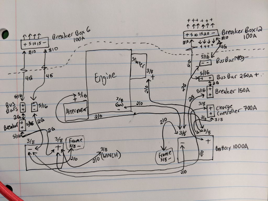
Second to last item on the hurry-up-and-start-it list is power cables. Doing my best to imagine future connections, calculate line loads & wire size to match, make it easy to work with in the future... all while moving forward carefully so I don't set fire to a whole day's worth of pay on stupid mistakes. I think I've gone thru a dozen+ sketches at this point... & I'm sure this one won't be the last:


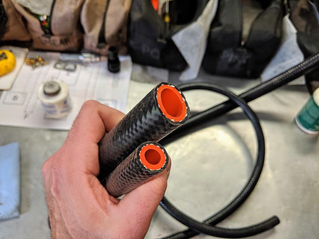
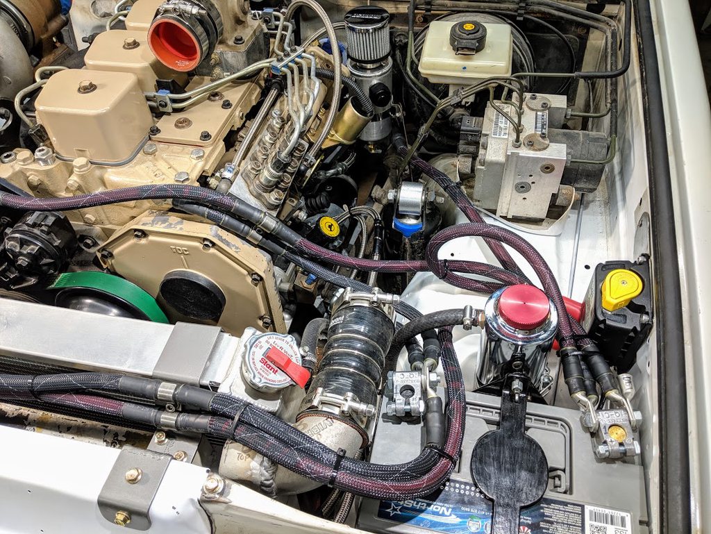
Everything I'm using in the engine compartment is tinned marine-grade wire (made by Ancor) with a relatively high strand count for flexibility. The primary level of connections is 2/0 AWG size between: the 2 batteries, starter, alternator, major ground point's (engine, frame, body, etc), charge controller, & circuit breaker switches:


I had some ideas to maybe build my own crimping device for these large cables, but after stumbling on a deal on a handheld hydraulic crimper I decided to give it a go:


It does a fantastic job! Made a few test pieces that I put thru all manner of abuse to see how well it holds. I feel plenty confident in them after cutting a few in half to see the strands & lug had achieved a uniform cold weld. The shrink tube may be overkill with such a strong mechanical connection, but I trust in the dual-layer Raychem adhesive lined tube to add an extra chemical connection to further reduce the likelihood of moisture & corrosion. These parts haven't been cheap (in money or time) & I want them to last!


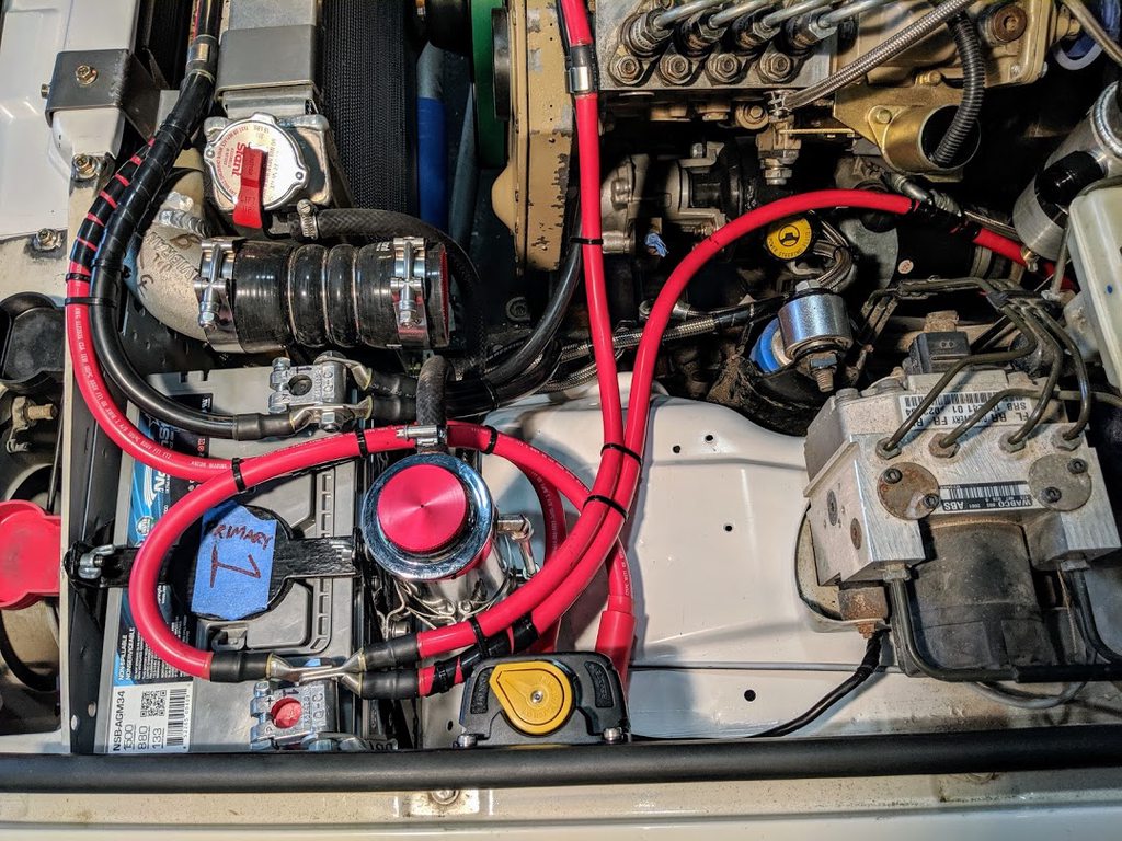
SO glad I found these "military style" battery post terminals (they do have big covers to match) with room for several large lugs, because after laying out my primary connections I nearly max them out:


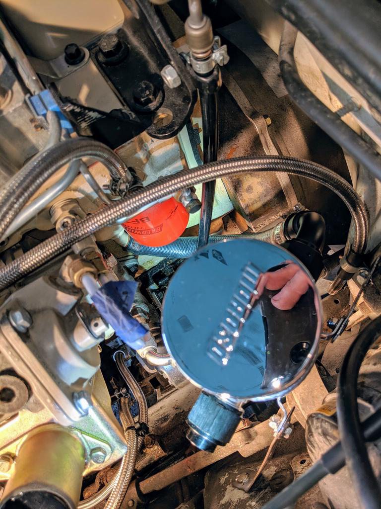
My charge controller is getting a temporary mounting on the driver's side fender while I work on these cables & wait for a rivet-nut tool to arrive so I can mount it solidly: (& properly plug that big duct taped hole from the old airbox right behind it)


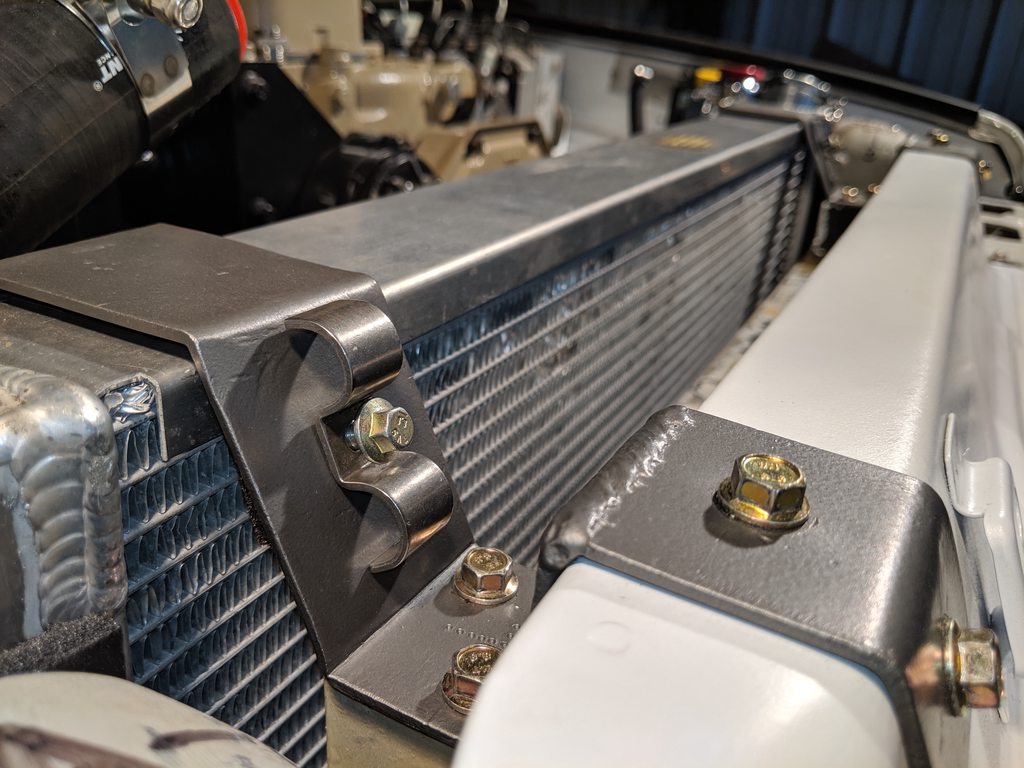
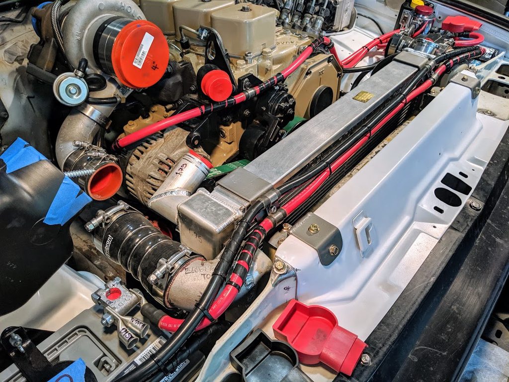
I'm taking advantage of the space above the coolers to run the main battery linking cables. My cooler's top brackets got a new hole, tapped to receive a pair of stainless double-hump clamps:


A few sections of protective spiral wrap & I think they'll fit thru there nicely:


I'm nearly done making all my primary 2/0 cables... man they're big! It's a good thing I didn't cheap out & run weld-lead wire or something, because the flexibility of this stuff has made building all these enjoyable, when it could've easily been a nightmare:
 
Last edited:

roverfanatic

Rank 0

Contributor I

I wish there was a better way to route all the different terminals/terminations to the battery posts. I have a 2 battery system and an isolator and I hate all the connects at the battery(s) It makes it so difficult to remove /replace batteries when needed. I used the same gauge wire and connector system on mine but not the same primary pole connector. Yours looks fantastic. I just saved the info on the Blue Sea unit. I like the functionality of it.

As always it's looking amazing!

Best,
Tony
 
  • Like
Reactions: Tinker

Tinker

Rank V
Launch Member

Off-Road Ranger I

2,357
West Michigan
First Name
Mike
Last Name
Klemish
Member #

5606

I wish there was a better way to route all the different terminals/terminations to the battery posts. I have a 2 battery system and an isolator and I hate all the connects at the battery(s) It makes it so difficult to remove /replace batteries when needed. I used the same gauge wire and connector system on mine but not the same primary pole connector. Yours looks fantastic. I just saved the info on the Blue Sea unit. I like the functionality of it.

As always it's looking amazing!

Best,
Tony
It's a handful for sure. But there's a good alternative for that in the form of a busbar. You could run a single big cable from the battery post to a busbar (blue sea example pictured below, but they come in all shapes & sizes) in a remote/better location, then link to it with all the remaining cables you had on your post previous. I'm planning to use several busbars: 1 negative + 1 positive each on either side of the engine bay, one side to run a circuit for "clean" power that'll feed loads like radios/computers that are sensitive to fluctuations, & the other side to run "dirty" power for loads that don't mind fluctuation or have extra high demands.


roverfanatic

Rank 0

Contributor I

I looked those up on Google after I posted this and there is definitely a lot to choose from. I had been planning on having a 4.6 from Warner shipped into replac4e the 3.9 with 400,000 miles on it (Still running well with admittedly less than new power) But I have decided instead to go all electric. I will be doing the lift and military wheel upgrade this year and then the conversion next year. I will post the build when it gets out of the planning stage.

FYI.....This might be a little overkill but on those 2.0 connectors, I added solder to them and then used the crimper. I have had those pull off before and although I cannot remember the circumstances of why I went with the "I tear everything I touch up " rule ...:)

I am going to private message you, I have some Youtube production questions for you, and I have already rambled on to long on this thread...

Lastly, I posted links and comments on your work to this thread to the other clubs I'm in or forums I am part of:

Land Rovers Only
Land Rover Forums
Texas Land Rovers
Southern New Hampshire Land Rovers Club
D1 Landy club [Facebook]
All Land Rover{Facebook]
Landy Zone UK
Donegal Overlanding [Facebook]

Best,
Tony
 
  • Like
Reactions: Tinker

Tinker

Rank V
Launch Member

Off-Road Ranger I

2,357
West Michigan
First Name
Mike
Last Name
Klemish
Member #

5606

I looked those up on Google after I posted this and there is definitely a lot to choose from. I had been planning on having a 4.6 from Warner shipped into replac4e the 3.9 with 400,000 miles on it (Still running well with admittedly less than new power) But I have decided instead to go all electric. I will be doing the lift and military wheel upgrade this year and then the conversion next year. I will post the build when it gets out of the planning stage.

FYI.....This might be a little overkill but on those 2.0 connectors, I added solder to them and then used the crimper. I have had those pull off before and although I cannot remember the circumstances of why I went with the "I tear everything I touch up " rule ...:)

I am going to private message you, I have some Youtube production questions for you, and I have already rambled on to long on this thread...

Lastly, I posted links and comments on your work to this thread to the other clubs I'm in or forums I am part of:

Land Rovers Only
Land Rover Forums
Texas Land Rovers
Southern New Hampshire Land Rovers Club
D1 Landy club [Facebook]
All Land Rover{Facebook]
Landy Zone UK
Donegal Overlanding [Facebook]

Best,
Tony
An electric Disco would be very interesting! Feel free to send it along, I'll gladly offer any advice I can. I keep wanting to post more of the build on other forums... but there are so many of them! Maybe I need to write a script to do it for me, to mirror it in relevant forums.
 

Tinker

Rank V
Launch Member

Off-Road Ranger I

2,357
West Michigan
First Name
Mike
Last Name
Klemish
Member #

5606

Battery cabling is complete! The extra lugs are placeholders for where I intend to run either leg of the 2 separated circuits (one circuit for "clean" power that'll feed loads like radios/computers that are sensitive to fluctuations, & the other side to run "dirty" power for loads that don't mind fluctuation or have extra high demands) & the battery terminals do have covers, seen here lower right:


Anywhere I thought things might rub got a wrap in high-temp flame-retardant spiral wrap, with no shortage of the high quality T&B ty-raps. Here you can see the pair of battery linking cables & the alternator feed wire running up the engine ground cable & across to my old 130-amp Rover unit:


The driver's side with the primary starting battery is a bit of a handful of wires, but I have them all lashed down enough to not foul on anything & not too much so removing things around them isn't a total pain:


The big switch mounted on the drivers wing is my automatic charging relay, with a switch to manually override or lockout it's operation. I had to patch the big hole there where the old V8's airbox snorkel passed thru with a stainless plate. Finally got my hands on a "nutsert" tool which made a breeze of mounting it on the sheetmetal... didn't know how much I needed one of those tools in my life!
 

InsertAliasHere

Rank III

Advocate II

Dude, all of this looks good! I haven't been on this forum in a while and just read through the thread. Everything seems thought through and not a hack job at all (unlike my engine swap which I'm basically expecting to burst into flames spontaneously). ha. Speaking of spontaneous fires, what are your plans for the electrics? Like all the little factory bits. I kept the rover ecu and harness to do non-engine/trans trans stuff but its kinda a messy nightmare.
 
Last edited:
  • Like
Reactions: Tinker

Tinker

Rank V
Launch Member

Off-Road Ranger I

2,357
West Michigan
First Name
Mike
Last Name
Klemish
Member #

5606

Dude, all of this looks good! I haven't been on this forum in a while and just read through the thread. Everything seems thought through and not a hack job at all (unlike my engine swap which I'm basically expecting to burst into flames spontaneously). ha. Speaking of spontaneous fires, what are your plans for the electrics? Like all the little factory bits. I kept the rover ecu and harness to do non-engine/trans trans stuff but its kinda a messy nightmare.
Oh I feel you with the potential disaster though! Even after all this work the fear of a runaway is real after all the turbo & fuel mods I've done. I think I might CNC a chunk of wood to fit the turbo inlet perfect with something funny engraved on it :sweatsmile:


My plan for the electrics is a complete overhaul... because I've already attacked every bit of the original wiring with cable cutters & yanked them out (there was no score settling, I swear). The new powertrain requires almost no wiring, so I'm kinda continuing the simplification & hardening throughout the whole chassis.

I like to say my inspiration for the wiring going forward is a hybrid between military aircraft & a research vessel. All my big wires are marine grade silicone covered tinned core cables, & all my small wires will be Raychem motorsports grade stuff. I'm using breakers in place of fuses everywhere aside from the alternator (because if it pops one it's a goner anyway, just there to save wire fires). All my big connectors are mil-spec lugs + clamps, & all the smaller wires will be linked using heavy duty Deutsch connectors. Every end's getting crimped, shrunk over with Raychem tube, & lengths covered with some aerospace braided sheath.

I've always wanted to build a vehicle's electrical system from the ground up, but I'm no McLaren F1 engineer, so it's been fun so far to learn & experiment as I go.
 

Tinker

Rank V
Launch Member

Off-Road Ranger I

2,357
West Michigan
First Name
Mike
Last Name
Klemish
Member #

5606

Oh & I may have got a bit ahead of myself saying I was "done" with the battery cables. After some discussion about protecting the alternator circuit & thinking more about abrasion risks I made some changes.

I was planning on using this braided sheath for the smaller wires, but was thinking why not use it on the larger wires? It's from the aerospace world: high temp, flame retardant, doesn't trap moisture, threaded to prevent unraveling, expands & shrinks over a large size range, but most importantly is very abrasion & cut resistant:


Here you can see the sealed fuse holder I patched into that long alternator wire that leads to the primary battery. It's sealed for both resisting corrosion & also ignition protection so if it blows with some force than any sparks that could start a fire are contained inside. I mounted it solidly to the brackets as close to the alternator as I could manage, & it holds a spare fuse inside which is handy. It's a slow breaking type that's overrated ~25% the max output rating of the generator:


I was a little worried this tight-weave braided covering may be too tight to identify the wire colors, but thankfully after installing it with sections of shrink tube on either end it was still easy enough to spot the color underneath:
 
  • Like
Reactions: roverfanatic