F350 CCSB

I guess the build page can continue as there are many items that need to be changed, added and also removed. So I guess I will continue to update this post. I might have to start an "adventures" post to share in my joy!
 
Last edited:
  • Like
Reactions: Viking1204
The idea of moving cool air within the sleeping area. Ideas, ideas, and ideas that are just more headache than they are worth. I could tell you all the ideas I had, but I'm a rock sometimes and my own worse enemy too boot. So After a lot of amazon returns, I just broke down and bought a MaxAir reversable fan with a rain guard. 1st trip I see how the money was well spent! I "love" the cool night air blowing inside!
 

Attachments

  • MaxAir (2).jpg
    MaxAir (2).jpg
    2.5 MB · Views: 37
  • MaxAir (1).jpg
    MaxAir (1).jpg
    2.4 MB · Views: 37
  • MaxAir (3).jpg
    MaxAir (3).jpg
    3.8 MB · Views: 37
  • MaxAir (4).jpg
    MaxAir (4).jpg
    2.9 MB · Views: 37
  • MaxAir (5).jpg
    MaxAir (5).jpg
    1.4 MB · Views: 37
  • MaxAir (6).jpg
    MaxAir (6).jpg
    2.8 MB · Views: 37
  • MaxAir (7).jpg
    MaxAir (7).jpg
    2 MB · Views: 37
  • Like
Reactions: Viking1204
Front, frame mounted hook points. The original location was no longer available so I hired a welder to mount directly on the frame! I guessing they will hold my 10k beast!
 

Attachments

  • Hook points (1).JPG
    Hook points (1).JPG
    2.1 MB · Views: 37
  • Hook points (3).JPG
    Hook points (3).JPG
    1.4 MB · Views: 37
  • Hook points (2).JPG
    Hook points (2).JPG
    2.1 MB · Views: 37
  • Hook points (4).JPG
    Hook points (4).JPG
    2.3 MB · Views: 37
  • Hooks point (1).jpg
    Hooks point (1).jpg
    1.7 MB · Views: 37
  • Hooks point (2).jpg
    Hooks point (2).jpg
    1.8 MB · Views: 37
  • Hooks point (3).jpg
    Hooks point (3).jpg
    1.7 MB · Views: 37
  • Like
Reactions: Viking1204
In the Beginning, there was adventure before OB and "the road chose me" entered into my life........I have come a long way!
 

Attachments

  • in the beginning.JPG
    in the beginning.JPG
    2.8 MB · Views: 42
  • Like
Reactions: Viking1204
Haven't updated this in a while but the new project "Save my fuel tank" has begun. My friend and I have designed a skid plate for my 56 gallon tank. When I swapped the OEM 24 gallon tank out, it exposed itself 3 inches below the frame rails. So I have been desperately wanting to give it a cover. So as of now, the 3/16" aluminum sheet has been purchased, the bend plan is set, the drain holes are set, the straps will be completed on the fly, and most importantly the welder is available. Now all I need is time to give up my truck.
 
  • Like
Reactions: Viking1204
During my last trip, I entered a very elite club! And I don’t mean the worry wart club of “what will break next!”
That’s impressive and very Landcruiser like. My 80 series had 382,000 on the original drivetrain when it sold to a collector. Compression test revealed a bit of wear - 159-143-146-144-143-131- once warmed up that 131 bumped up to 139.

When I purchased this truck in 2019, I drove 130 miles and the high pressure oil pump detonated. Block to turbo replacement so the chassis has 300k but the motor has 70k
 
  • Like
Reactions: Viking1204
Let the fuel tank skid plate construction begin! Width is cut and sides lip bent. A little cutting here, a little there, some welding and hole cutting. Then is all goes well, making the mounts! MTF
 

Attachments

  • media.jpg
    media.jpg
    448 KB · Views: 30
  • Like
Reactions: Viking1204 and MOAK
1st planning meeting with the skid plate. A few adjustments are definitely needed. Tomorrow, cut outs for frame rail fuel pump, front angle to tie into xfer case plate, tapering the back drivers section to match the tanks extremely odd shape. Then on to drain holes and straps. Fun times making this on the fly!
 

Attachments

  • 1st fitting (1).jpg
    1st fitting (1).jpg
    1.6 MB · Views: 29
  • 1st fitting (2).jpg
    1st fitting (2).jpg
    1.6 MB · Views: 29
  • 1st fitting (3).jpg
    1st fitting (3).jpg
    1.5 MB · Views: 29
  • Like
Reactions: Viking1204
A little cut here, weld here...getting ready for the brackets.
 

Attachments

  • 2nd fitting (1).jpg
    2nd fitting (1).jpg
    370.7 KB · Views: 30
  • 2nd fitting (3).jpg
    2nd fitting (3).jpg
    346 KB · Views: 30
  • 2nd fitting (4).jpg
    2nd fitting (4).jpg
    328.4 KB · Views: 29
  • 2nd fitting (6).jpg
    2nd fitting (6).jpg
    357 KB · Views: 29
Well lets just say that the "modular" plan worked and I was able to remove everything in 2 hours. The only thing I needed help with was the cap. Its light but 3 guys were able to handle it with ease. The reason I took everything apart is that I needed the 5th Wheel to move my RV. New tires were needed after sitting for 3 years. :-(

Anyways, it was time to re-evaluate all the connections, the wire placement and add a few things that were after thoughts. I never liked the rear electrical connector/switch panel as it looked wonky. I also needed to trace down the short in the rear Light bar. It ended up being a switch was melted. The rear panel template is cut out and now comes the placement of the other connections.

So I was researching wireless remotes for the winch, lights and was going to go with a piece-mail approach of individual items but after hours of trying to evaluate if they all would work together, I decided to just go with AUXBEAM AC-1200. Remote and app ready! Solves all the problems except having to replace the rear panel of the power box. All is well with the plan and it will be back together soon.

The real fun comes from re-wiring all the lights to the rear. R&D gets costly but its all in good fun!
 

Attachments

  • AUXBEAM wiring.jpg
    AUXBEAM wiring.jpg
    83.2 KB · Views: 17
  • 20251219_190817127_iOS.jpg
    20251219_190817127_iOS.jpg
    4.9 MB · Views: 17
  • 20251223_010451887_iOS.jpg
    20251223_010451887_iOS.jpg
    2.6 MB · Views: 17
  • 20251223_011520433_iOS.jpg
    20251223_011520433_iOS.jpg
    1.2 MB · Views: 17
  • 20251223_011535350_iOS.jpg
    20251223_011535350_iOS.jpg
    1.8 MB · Views: 17
  • 20251223_014043236_iOS.jpg
    20251223_014043236_iOS.jpg
    2.5 MB · Views: 17
  • 20251223_015350346_iOS.jpg
    20251223_015350346_iOS.jpg
    2.4 MB · Views: 18
  • 20251224_142050020_iOS.jpg
    20251224_142050020_iOS.jpg
    2.5 MB · Views: 18
  • 20251224_203226085_iOS.jpg
    20251224_203226085_iOS.jpg
    2.4 MB · Views: 18
  • 20251224_203242289_iOS.jpg
    20251224_203242289_iOS.jpg
    1.8 MB · Views: 18
  • Like
Reactions: Viking1204
I think I said R&D is costly....Yeah, its also time consuming. As with any plan, things change. Add in my sudo-OCD of "wanting to do it right" the first time, a ton of coffee, I have come to realize that I do not always think of everything when I start. So "change-Switch!" Pun intended.
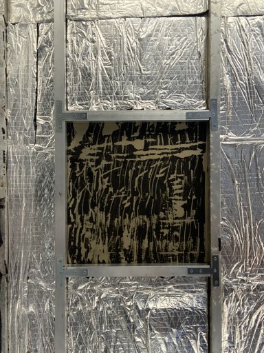
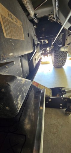
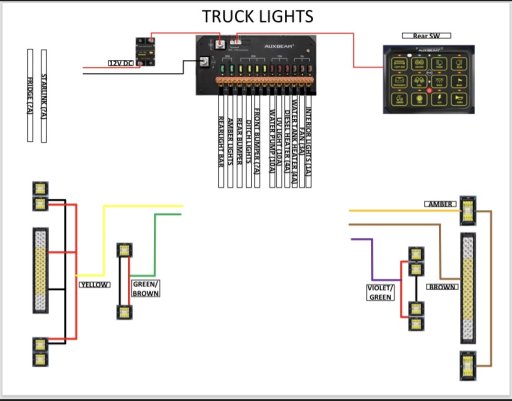
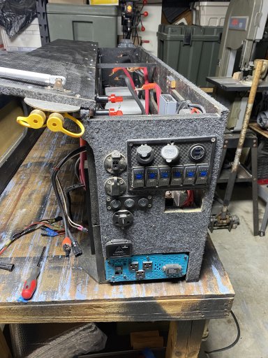
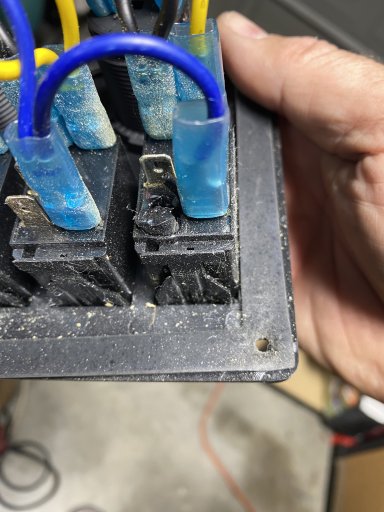
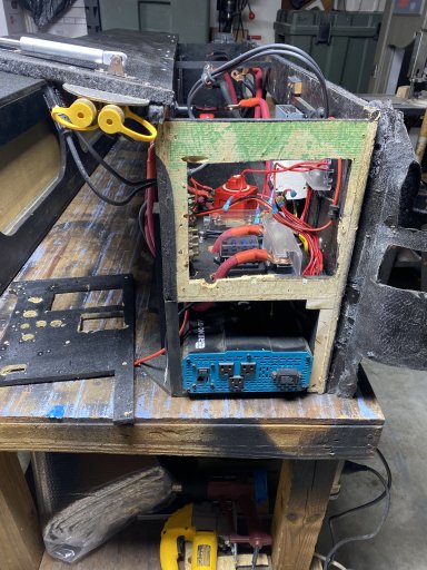
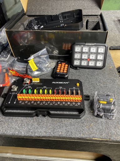
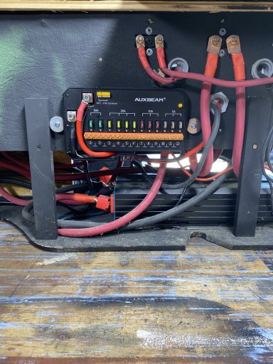
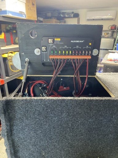
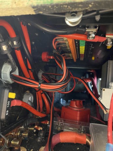
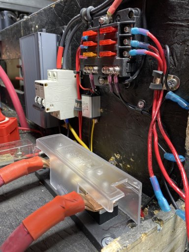
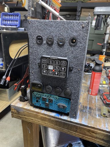
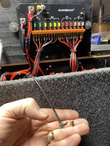
It is hard to explain a visual concept but in the previous post, you see the mounted auxbeam controller. It is 10" wide so placement is very difficult in a small width battery box. I stood there for a long time thinking it thru, got another coffee and went to work. After I made the cables for the power/ground, and the 3 water box wires, got them all cinched down and then caught my mistake. The proverbial Homer Simpson DUH hit me. Imagine the following: The battery box fits in the bed and covers the drivers wheel well. It is tucked up against the side and held in place by the center drawer system. There is zero access to the road side of the battery box once it is installed. So "riddle me this batman" if fuse blows, how to I change it if it is hidden from view.
I scratched my head and went inside for another cup O' Joe.

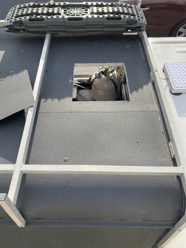
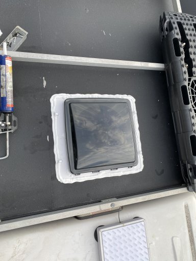
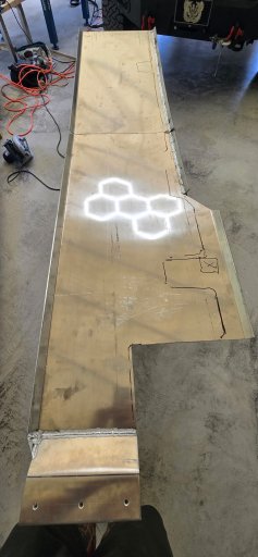
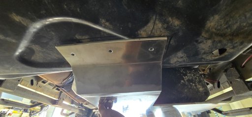
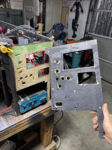
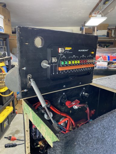
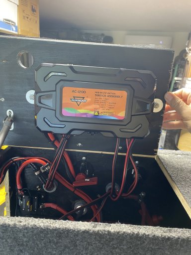
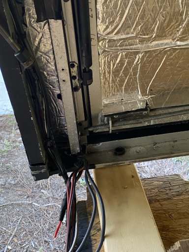
A new day, a new plan! Not sure why I didn't think of this location first but the controller fits nicely mounted on the inside of the access door. I guess the bending of the wires when I lift the lid is one reason I didn't choose it. After staring at it for what seemed like at least 2 cups O' Joe, I was pondering the flex of wires when the lid was raised/closed, the effects of road bouncing and vibration, yada, yada, yada.....Finally I did a test fit and was happily surprised that not only does it fit well, the amount of wire movement when opening/closing the lid is a lot less than I thought. So we are moving forward.

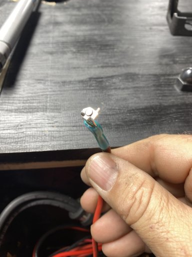
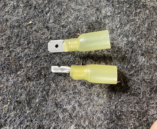
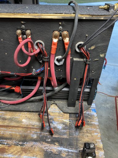
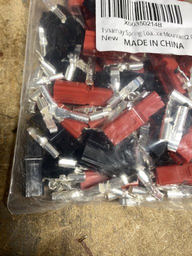
I will say this, stranded wire sucks without using some sort of ferrule terminals. They just didn't stay secure during the lid closing test. Instead of buying/waiting for amazon to deliver ferrule cups, I made some myself! Genius my wife calls me! Industrious, I say if you add me to a box of rocks.

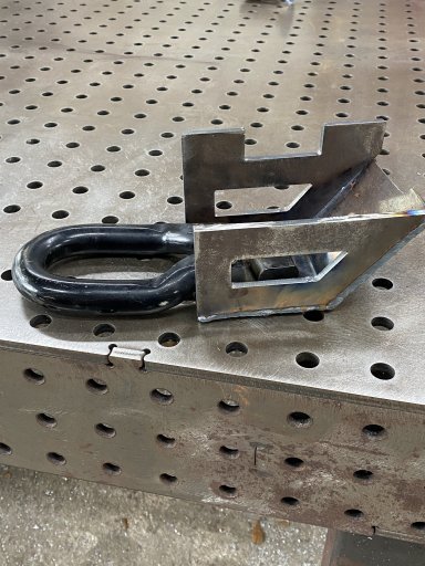
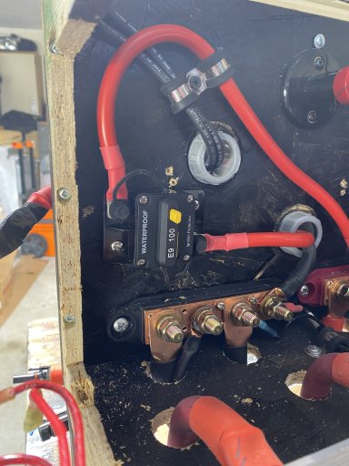
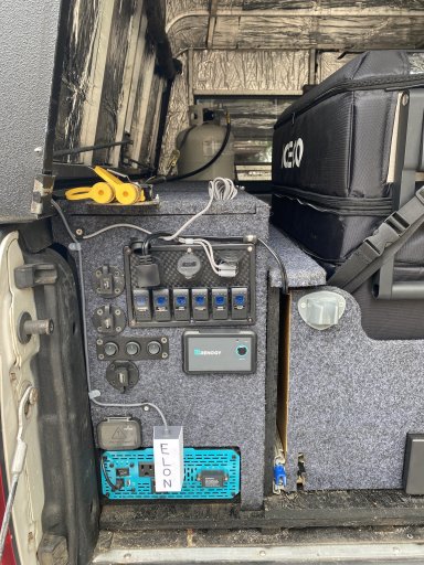
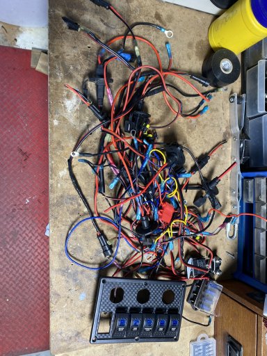
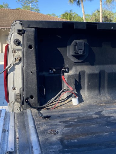
As the wiring was taking shape, thoughts went back to install/removal of the battery box, the connections for the cap and running the front bumper lights to the rear. All are challenging when they are in your mind but version 1 are these small anderson connectors I bought and never used. It will allow me to disconnect and pull them thru the small bed rail hole that transitions to the cap. More re-wiring when the cap goes back on but that is another day and cup O' Joe later. Without further a-do....eye candy!
 

Attachments

  • Old electric panel.JPG
    Old electric panel.JPG
    3 MB · Views: 15
  • ferrule terminals.JPG
    ferrule terminals.JPG
    4 MB · Views: 15
  • mounting with wires.jpg
    mounting with wires.jpg
    2.4 MB · Views: 15
  • mounting.jpg
    mounting.jpg
    1.9 MB · Views: 15
  • quick disconnect for Cap wires.jpg
    quick disconnect for Cap wires.jpg
    2.5 MB · Views: 16
  • cover cut out.jpg
    cover cut out.jpg
    1.8 MB · Views: 16
  • lid closed-side view.jpg
    lid closed-side view.jpg
    2 MB · Views: 16
  • removed wire.jpg
    removed wire.jpg
    2.5 MB · Views: 15
  • anderson connectors.jpg
    anderson connectors.jpg
    2.1 MB · Views: 15
  • bed rail.jpg
    bed rail.jpg
    3.3 MB · Views: 15
  • cap rail.jpg
    cap rail.jpg
    1.9 MB · Views: 15
  • drivers side.jpg
    drivers side.jpg
    1.8 MB · Views: 15
Final calling all the prep work complete. Finished the battery box rewire task, cleaned up the wiring on the water box, rewired the 3-front bumper lights and the ditch lights to the rear entry point. Now all I have to do is move my RV, finish off the gravel driveway with RAP (recycled asphalt), move the rv back and then I can start piecing my camper back together. There is a rally point for the FAT on the 16th that I am trying to make. Wish me luck.
 

Attachments

  • media.jpg
    media.jpg
    336.7 KB · Views: 11
  • media.jpg
    media.jpg
    468 KB · Views: 11
  • media.jpg
    media.jpg
    369.6 KB · Views: 11
  • Like
Reactions: Viking1204
Looks great

I am in the process of doing something similar. Is there a reason you did not run the wires that go up into the bed, through the stake pocket hollow, instead of up through the bed floor? I am thinking of using the stake pocket tower to get my wiring in to minimize holes in the bottom of the bed.

Shawn

Thanks! Unfortunately my 2014 doesn’t have stake pockets. Most importantly, Im never getting rid of this truck so the holes don’t bother me. Actually the only holes in the floor are for the diesel heater exhaust/fresh air pipes. and a 1/2” water tank low point drain. I did need to pop 2 holes in the rear part of the top rail due to a design flaw in the trailing edge of the 2 wheel well boxes. The battery box (drivers side)and diesel heater/tool box (passenger) that covers the wheel wells. Instead of rebuilding the boxes, in goes the holes! They are covered by the cap rails and I use grommets to protect the wires! Small price to pay I guess!
My lessons learned are an incredible tale of trial and error and lots of money!! Even with the best laid out plan, I changed a few things that I wished I thought of in the first version!

Best of luck with your build and dont forget to create a page so we can follow your progress! Oh, if you want a small form factor UV light for your water supply, dont buy guzzleH20’s expensive setup. I found that the manufacturer sells it online at Lowes! Shocked me too!
 

Attachments

  • media.jpg
    media.jpg
    89 KB · Views: 5