
Advocate III
- 5,584
- First Name
- Michael
- Last Name
- Rose
- Member #
-
20990
- Ham/GMRS Callsign
- W7FSB
- Service Branch
- US ARMY Retired

Advocate III
20990

Advocate III
20990
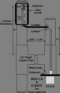
Antenna is up... I built my own design J-Pole... I used about 4 different write-ups to come up with my own solution. Sorry I didn’t take any pictures during the build... I have one thing left to do tomorrow and will take pictures of it... but until then I will describe what I did.Mike,
Did you already get your antenna set up? What did you go with?

Advocate III
20990

Advocate III
20990
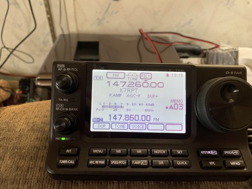
My antenna has been up a month now. Still getting a flat 1.5:1 SWR a crossed both the 2Meter and 70cm bands it was designed for..lVery cool! And thanks for the write up. That’s very similar to what I am planning to build.

Advocate III
20990

Advocate III
20990

Advocate III
20990






Advocate III
20990

Advocate III
20990

Advocate III
20990

Advocate III
20990
DC would have 0 Hz. Just buy a 110v DC power supply. Check out HRO they have different Amp rated supplies for radios. look in the radios manual,and see what the max draw during transmitting to see what size you will need. Older model power supplies had transformers and what they call a bridge rectifier, thats what converts ac to dc and were expensive to mfg. The newer model use what they call a switching power supply. 2 transistors that turn on and off really fast instead of a transformer. They are much cheaper to manufacture. The trade off is the cheaper ones that don’t have good filtering and shielding create noise, this is called RF interference. It is transmitted thru the air. It can “bleed” back into wiring and also radio reception. You could try a filter cap or a RF choke but you are still going to get a buzz. This is why you see so many guys with noise problems with cheap off-road led lights.With the furnace running I’m not able to get a steady Hz reading... I am however able to get 12.45 VDC
With furnace off i am getting 119.99 Hz and a steady 12.3VDC.

Advocate III
20990
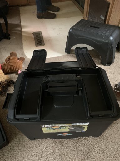
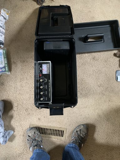
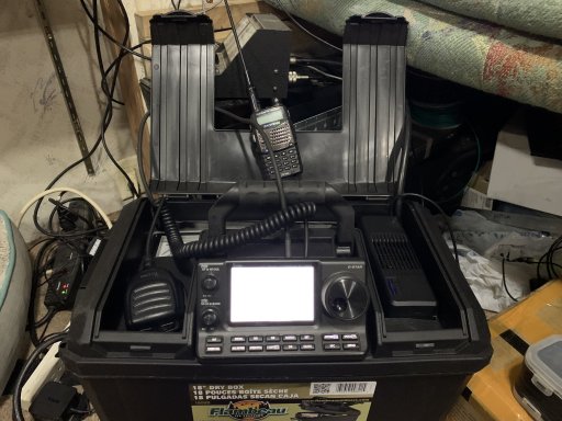
Late to the party... I have a 65 amp Continuous Duty Filtered inverter that I had laying around, I get 0 noise from it, and its mounted next to my rig inside the Go-Box... In fact it works so good as a power supply a couple of my friends use their travel trailers as their Mobile Ham Shack, that when they saw my setup they ran off and bought the same inverter for their RVs.DC would have 0 Hz. Just buy a 110v DC power supply. Check out HRO they have different Amp rated supplies for radios. look in the radios manual,and see what the max draw during transmitting to see what size you will need. Older model power supplies had transformers and what they call a bridge rectifier, thats what converts ac to dc and were expensive to mfg. The newer model use what they call a switching power supply. 2 transistors that turn on and off really fast instead of a transformer. They are much cheaper to manufacture. The trade off is the cheaper ones that don’t have good filtering and shielding create noise, this is called RF interference. It is transmitted thru the air. It can “bleed” back into wiring and also radio reception. You could try a filter cap or a RF choke but you are still going to get a buzz. This is why you see so many guys with noise problems with cheap off-road led lights.

Advocate III
20990

Influencer I
I bought one of the nanoVNA's a few weeks ago. WOW!! I'm already a fan.Raspberry Pi and an SDR - download and run free open source software. Been using mine as a temporary APRS gateway and as a weather balloon tracker. Lots of neat possibilities for less than a hundred bucks. NanoVNA - analyzer for homebrew antennas for around a hundred bucks. Very cool tool if you want to build antennas.

Advocate III
20990
I just got one myself... nifty tool... check out NanoSaver, it’s free software for the device to be able to manipulate the NanoVNA with a larger screen and a mouse.I bought one of the nanoVNA's a few weeks ago. WOW!! I'm already a fan.

Influencer I
I'll have a look!I just got one myself... nifty tool... check out NanoSaver, it’s free software for the device to be able to manipulate the NanoVNA with a larger screen and a mouse.
