
Navigator I
I posted this on another forum for Land Rovers, but feel it's just as applicable for OB. Photo heavy...
After a significant amount of researching, I haven't seen a good discussion on adding a secondary battery to the Disco. So, I figured I would document my efforts. This is an ongoing project since it's going on about two weeks worth of research/design.
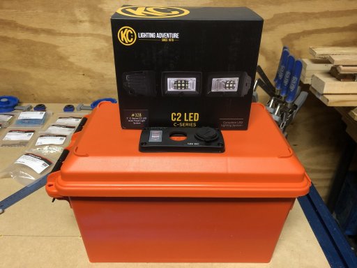
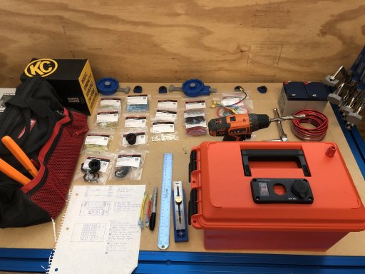
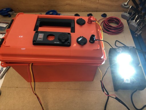
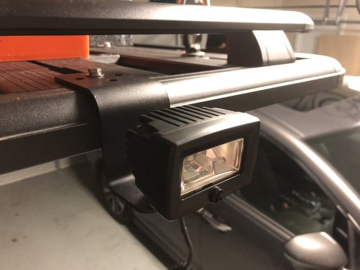
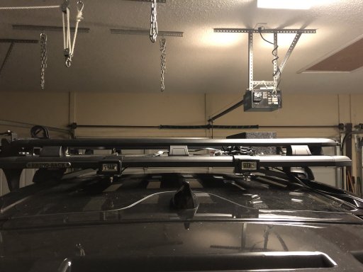
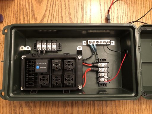
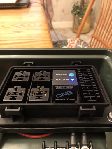
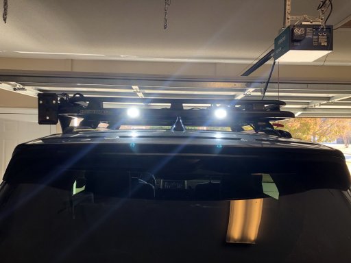
I started down this path to power the lights I plan to add to the roof rack. I am looking at a set of KC Gravity Pro6 lights and a couple of sets of the C-Series Area flood lights (#328). The goal was to keep the removal of the roof rack easy without complicating the disconnecting of power. So, I thought I would build a box for the battery and mount it to the roof rack. This would house the battery(ies) and the Trigger 2100 wireless switch. If I put it on the roof rack, I wouldn't have to deal with pulling headliners, drilling holes in roofs, etc. Seemed like a good idea. But, I wouldn't have a way to charge it if I was out camping or away from electricity. Yes, I could charge it with a battery charger when I was home, but I still needed enough juice to keep up with nightly discharges.
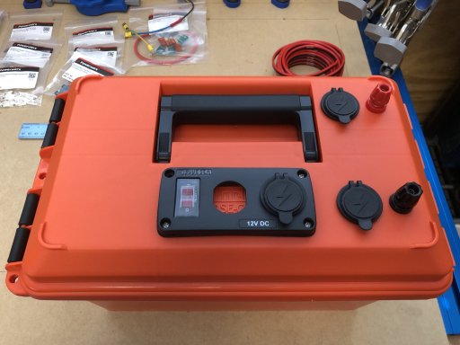
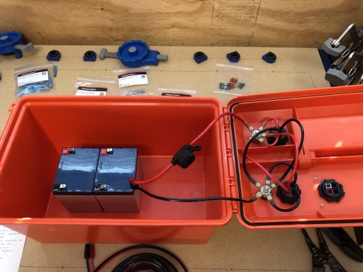
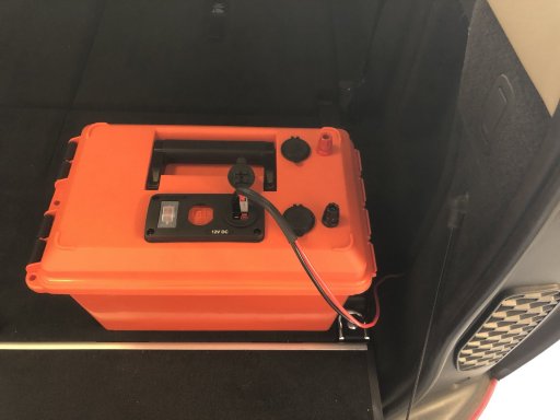
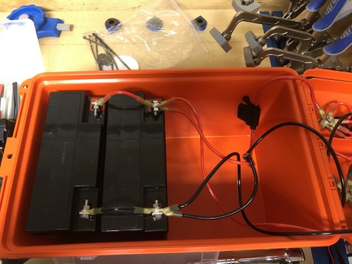
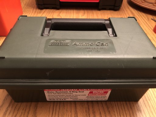
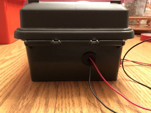
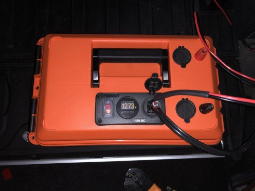
This is where it gets fun! The Pro6 set I am looking at pulls about 13A, and the two sets of floods pull about 6.4A. I wanted to be able to have two nights worth of runtime, so I figured I would need to run the Pro6's for about 4 hours and the floods for another 3 hours per night. Quick math says I need a 72Ah worth of current. To keep at little extra current just in case, I rounded up to 80 Ah. For two nights, that makes it a whopping 160Ah battery! Because I would be mounting this in a case and I would be completely (potentially) discharging the battery, I need a Sealed Lead Acid, deep discharge battery. The case I'm using is an MTM AC35. This also limits the form factor of the battery I can put in the case. These type of batteries are not cheap. Maybe I could get by with a smaller battery? And, that led me down the path of figuring out how I could charge the battery while the car was running...
I knew I could easily build a cable to connect the box on the roof to the battery, I just wasn't sure how to get it to the roof from inside the car without compromising the wading capability. Which means I had to start pulling things apart.
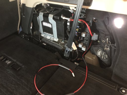
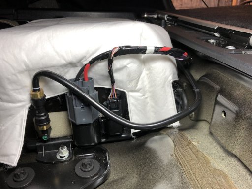
Battery housing
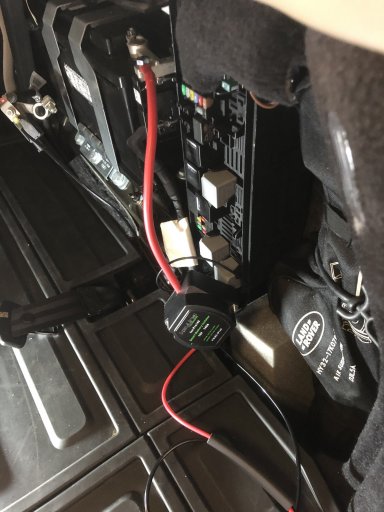
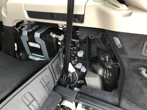
The battery housing is located at the rear passenger quarter panel. I also needed a way to separate the starting battery from the secondary battery while still being able to charge it.
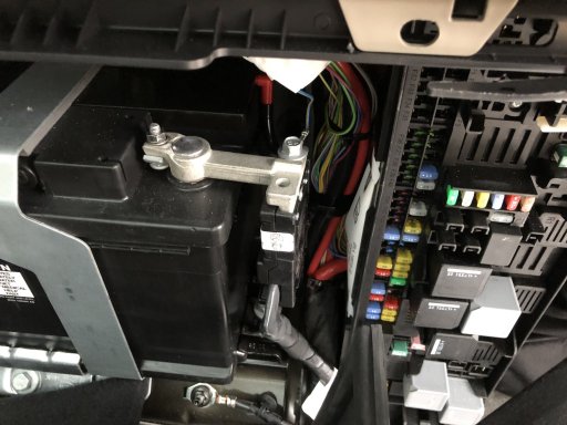
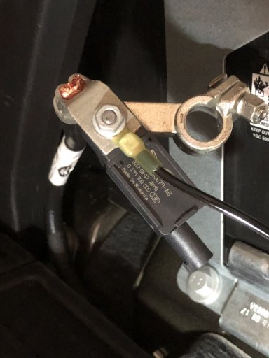
Spare terminal for positive
There is a spare screw hole for adding additional power loads. This is where I am adding the battery isolator I bought off of Amazon. With the isolator providing a charging voltage without allowing the starting battery to be drained from anything connected to the second battery, I can drain the secondary battery and still be able to start the car. Definitely a requirement!
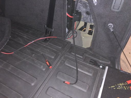
After researching on DigiKey for parts to make waterproof connections and provide covers to keep unmated connections covered, I settled on a set of two prong circular connectors. I started looking for spots to get the power to the outside of the car. After pulling up the back panel where the spare is, I found a spot I thought would work.
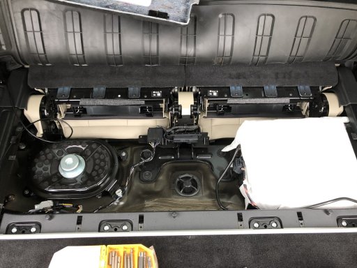
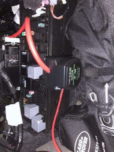
Under rear panel behind 3rd row
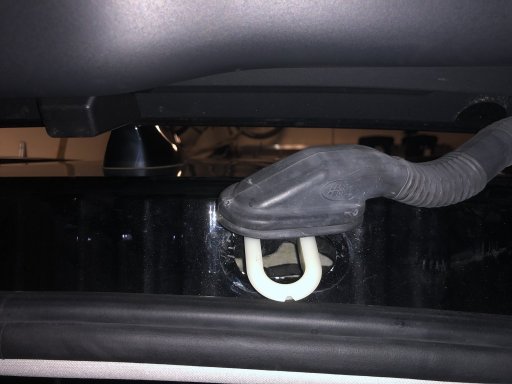
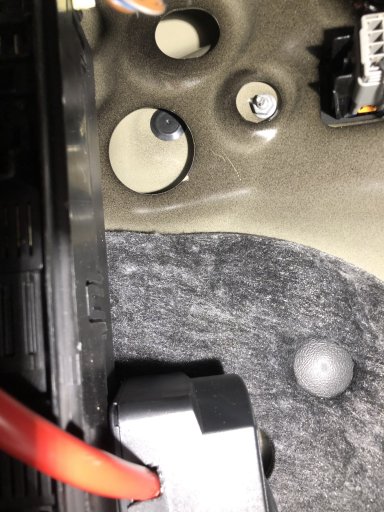
Rubber grommet behind air compressor
The rubber grommet is to the right of the air compressor.
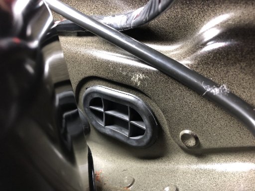
Close up of rubber grommet
The rubber grommet seems to be a good spot to cut a hole, run a wire, and reseal with some silicone. That would allow me to get to the spot where I wanted to mount the outside connection. Since I was planning to only plug the battery box in after a night of use, I was going to make a cable that would run from the back up to the roof just hanging there while driving to recharge the battery.
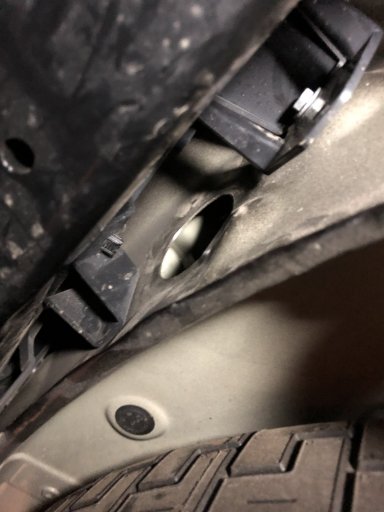
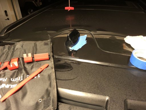
Opening from under the car where rubber grommet would come through
This is on the outside of the car, underneath. The grommet doesn't fit in this hole, but another one hole behind this one.
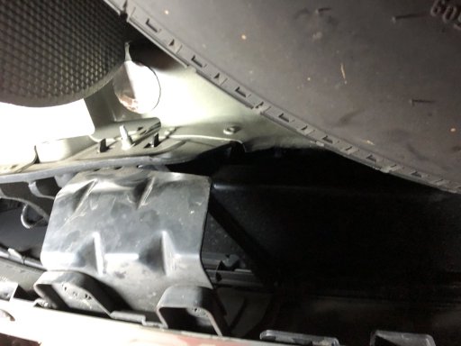
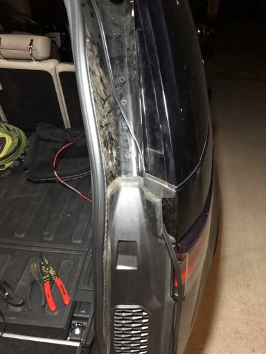
Bracket that would be drilled to mount connector
This is where I would mount the connector. It is on the inside, passenger side of the bumper.
While this would check off the easy removal and recharging requirements, it does not look good or seem safe if it gets caught by a branch or other object. It was during this timeframe that I started to think, what if I wanted to put some extra stuff in the car (i.e., Dometic CFX75 or ARB 50)? New requirements mean back to the drawing board…
After a significant amount of researching, I haven't seen a good discussion on adding a secondary battery to the Disco. So, I figured I would document my efforts. This is an ongoing project since it's going on about two weeks worth of research/design.
I started down this path to power the lights I plan to add to the roof rack. I am looking at a set of KC Gravity Pro6 lights and a couple of sets of the C-Series Area flood lights (#328). The goal was to keep the removal of the roof rack easy without complicating the disconnecting of power. So, I thought I would build a box for the battery and mount it to the roof rack. This would house the battery(ies) and the Trigger 2100 wireless switch. If I put it on the roof rack, I wouldn't have to deal with pulling headliners, drilling holes in roofs, etc. Seemed like a good idea. But, I wouldn't have a way to charge it if I was out camping or away from electricity. Yes, I could charge it with a battery charger when I was home, but I still needed enough juice to keep up with nightly discharges.
This is where it gets fun! The Pro6 set I am looking at pulls about 13A, and the two sets of floods pull about 6.4A. I wanted to be able to have two nights worth of runtime, so I figured I would need to run the Pro6's for about 4 hours and the floods for another 3 hours per night. Quick math says I need a 72Ah worth of current. To keep at little extra current just in case, I rounded up to 80 Ah. For two nights, that makes it a whopping 160Ah battery! Because I would be mounting this in a case and I would be completely (potentially) discharging the battery, I need a Sealed Lead Acid, deep discharge battery. The case I'm using is an MTM AC35. This also limits the form factor of the battery I can put in the case. These type of batteries are not cheap. Maybe I could get by with a smaller battery? And, that led me down the path of figuring out how I could charge the battery while the car was running...
I knew I could easily build a cable to connect the box on the roof to the battery, I just wasn't sure how to get it to the roof from inside the car without compromising the wading capability. Which means I had to start pulling things apart.
Battery housing
The battery housing is located at the rear passenger quarter panel. I also needed a way to separate the starting battery from the secondary battery while still being able to charge it.
Spare terminal for positive
There is a spare screw hole for adding additional power loads. This is where I am adding the battery isolator I bought off of Amazon. With the isolator providing a charging voltage without allowing the starting battery to be drained from anything connected to the second battery, I can drain the secondary battery and still be able to start the car. Definitely a requirement!
After researching on DigiKey for parts to make waterproof connections and provide covers to keep unmated connections covered, I settled on a set of two prong circular connectors. I started looking for spots to get the power to the outside of the car. After pulling up the back panel where the spare is, I found a spot I thought would work.
Under rear panel behind 3rd row
Rubber grommet behind air compressor
The rubber grommet is to the right of the air compressor.
Close up of rubber grommet
The rubber grommet seems to be a good spot to cut a hole, run a wire, and reseal with some silicone. That would allow me to get to the spot where I wanted to mount the outside connection. Since I was planning to only plug the battery box in after a night of use, I was going to make a cable that would run from the back up to the roof just hanging there while driving to recharge the battery.
Opening from under the car where rubber grommet would come through
This is on the outside of the car, underneath. The grommet doesn't fit in this hole, but another one hole behind this one.
Bracket that would be drilled to mount connector
This is where I would mount the connector. It is on the inside, passenger side of the bumper.
While this would check off the easy removal and recharging requirements, it does not look good or seem safe if it gets caught by a branch or other object. It was during this timeframe that I started to think, what if I wanted to put some extra stuff in the car (i.e., Dometic CFX75 or ARB 50)? New requirements mean back to the drawing board…