Electrical Power Upgrades-2016 Jeep JK

  • HTML tutorial

Dur66

Rank II
Launch Member

Contributor III

Good Morning,
I've looked through these threads and have not been able to find any that talk about upgrades to run electrical accessories.

I have a 16 Jeep JK and would like to start upgrades in order to run an ARB refrigerator, a small fan and maybe install solar in order to be self-sufficient on the road.
Since I did not order the Mopar sub-woofer system, I do not have a power outlet in the back. I would like to install a 9V power outlet and a 110v plug which can be switched on/off to run accessories.

I'm planning to install the Genesis Offroad dual battery setup with Odyssey batteries. That is the only part of this I'm certain of so far.

Has anyone out there done this?
Thanks, Durwin
 
  • Like
Reactions: Michael G.

Seppy

Rank V
Launch Member

Enthusiast III

2,191
Cambon Avenue, Saint James, NY, USA
First Name
Joseph
Last Name
Cosentino
Member #

12370

I installed an Apollointech, 8 switch system. Less expensive than an Spod.


There are youtube video's on the install. If you take your time and route the wires neatly, you can do it in an hour. It's very simple. From there you can add anything you like.
 
  • Like
Reactions: ASRussell

RootedWanderers

Rank V
Launch Member

Advocate II

2,306
Pelham, Alabama 35124
First Name
Wayne
Last Name
Sullivan
Member #

5808

I have the Apollointech for my switch pod and accessories connectivity, I too plan on going the route of the Genesis system for my dual battery, I haven't done it yet though.
 

toxicity_27

US MidWest Region Member Rep
Launch Member

Member II

3,278
Minnesota
Member #

0656

I'm running the Genesis system with dual Odyssey Extremes. I also have the sPod system. I eventually plan on adding some solar (quite a ways down the road), but also have a few lights, winch, air compressor, and an Engel MT45 fridge. I plan on adding the Goose Gear plate system, and installing some outlets with that, as well as adding a few lights to the AEV tire carrier I just ordered. For the 110v plug you can look into an inverter that's pure sine wave (I've thought about adding one), and for the regular 12v outlet you can plug into some wires that run in the rear. I think Venture4wd has a video of some outlets he hooked up into the factory wiring.
 

Texassailor

Rank III
Launch Member

Contributor III

684
Austin, TX
Member #

8476

Still running the stock starting battery in my '17 JKUR. I've added an sPod (8-switch) to run my auxiliary lights, comms (CB & Ham), and winch solenoid (cut-off).

A couple of months ago, I purchased a SnoMaster 56 dual zone fridge/freezer. Trying to run it off of the 12V plug in the rear just didn't work given it is probably 16-18 ga wire. The fridge pulls between 2.4 and 4.9 amps. So I added a two 34R-PC1500T Odyssey Extreme batteries in the rear along with the fridge. Here is my electrical setup:


I don't have it completely wired yet as I am swapping out my PWM controller with my new 40 amp MPPT controller

My two Odyssey batteries are being held down by a very high quality cage from Artec Industries. This cage keeps the batteries FIRMLY in place using 10 gauge steel plate.

And, finally, my folding solar panel (120W) from ACOPWER. As I said, I ditched the included 10A PWM controller for a 40A MPPT controller. I'd like to get another 120W folding panel from ACOPOWER. Waiting to hear back from them on being able to sell the panel ONLY . . . without the PWM controller.


The MPPT controller has been a great upgrade as it converts the higher voltages produced by the panel into more amps to the battery.

Once I get everything "neatly" and "permanently" installed, I'll provide photos. Until then, it is a continuing work in progress. I've only had the MPPT controller installed for 24 hours. Huge improvement!
 

Texassailor

Rank III
Launch Member

Contributor III

684
Austin, TX
Member #

8476

I just now realized you have a JK and not a JKU. You'll be strapped for space in the rear for a fridge, won't you? Have you removed the rear seat? My son runs his JKR with the rear seat removed most of the time.
 

Dur66

Rank II
Launch Member

Contributor III

Thanks everyone. Yes, it's a 2door. I have an ARB 37 L fridge. The rear seat got removed after I brought the Jeep home. I'm wondering if it's worthwhile to get the ARB fridge slide. Yes, please do post pics.
Durwin
 
Last edited:

Kumayama

Rank II
Launch Member

Enthusiast I

434
Ridgemark, CA, USA
First Name
Lyn
Last Name
Mangiameli
Member #

11182

Ham/GMRS Callsign
KM6OMM
My working list for 2015 JKUR Electrical Power Distribution
BS= Blue Sea
All wire is marine grade tinned, copper strand

Battery Direct Power:
-ARB dual compressor (two 30 amp maxi fuses inline below breakers)
-ARB refrigerator (15 amp fuse inline below breakers) 8 gauge wire
-Susquehanna relay/flicker headlight control box ( fuse inline)
-sPod power distribution (50 amp inline resetting circuit breaker, 8 gauge wire)
-Driver side ignition triggered solenoid switched power (BS 12 fuse block, 8 gauge wire with 80 amp? inline resetting circuit breaker)
-Passenger side ignition triggered, solenoid switched BS 8 fuse block (unfused power from Driver Side BS 12 fuse block via 8 gauge wire)
-Passenger side constant power (BS 6 fuse block via 60 amp circuit breaker)
[8 gauge positive; 6 gauge negative wires to battery run through the large firewall pass thru on the passenger side that comes out just below the battery tray. Requires removing the batteries, etc. to access the pass thru from the engine compartment side. 6 gauge negative ends below dash at 1 in/3 out distribution brick with 8 gauge ground wires continuing to passenger constant and passenger switched blocks and driver rear RIGrunner]
-Engine compartment constant power distribution (BS 4 fuse block)
-Rear power distribution box, constant & relay switched (via 50 amp circuit breaker)
-Ham Radio power distribution [Powerwerx ITS - 12 timer/voltage disconnect module / Rigrunner 4005h 1 in, 5 out fused PowerPole connectors via unfused 8 gauge positive line from passenger BS 6 fuse block and 8 gauge line to grounding brick].
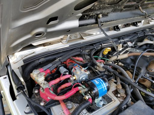
-Winch (Warn circuit breaker)
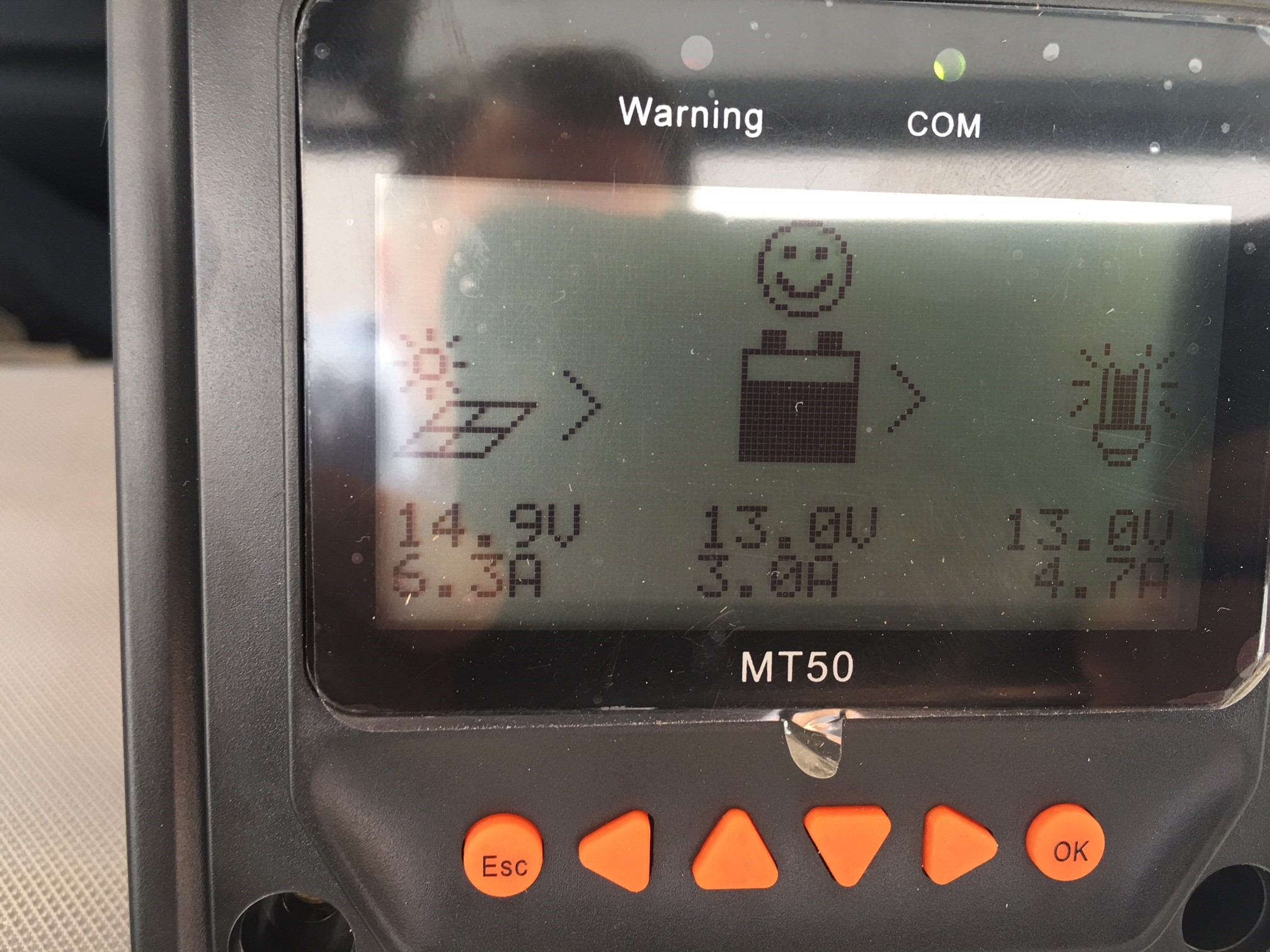
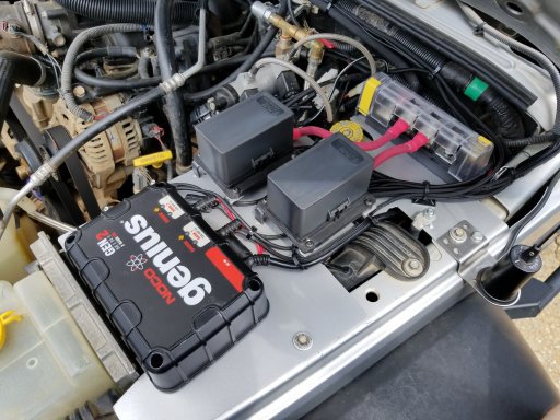
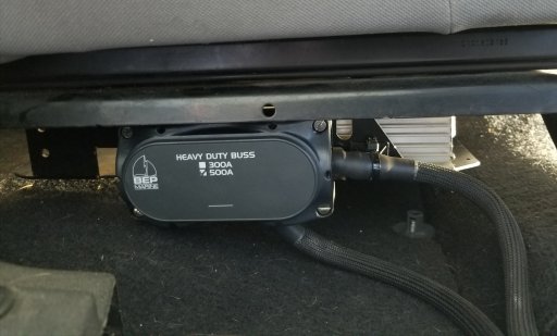
High-amp accessories like the winch go to the large center studs on the Genesis power and ground bus bars. When the batteries are connected, this will use the combined capacity of both batteries, spreading the load of the winch across both batteries. Once the cranking battery drops below 12.7v for 1 minute, all of the accessories that are connected to the power and ground buss bars will run from the aux battery only. This protects the cranking battery from being drained by the accessories. The batteries will remain isolated until the cranking battery is back up above 13.2v for 2 minutes, then they will automatically be reconnected. The G Screen monitor can display the voltage of each battery and whether they are connected or isolated. [Shane, Genesis Offroad July 13, 2017]
Cole Hersee 48530 series smart isolator between the two Optima Yellow top batteries


External Auxiliary Lights:
sPod (constant power through individual sPod 40 amp relays with individual Carling switch triggers in interior roof switch panel)
-Rock lights (combined red & white)
-Driving lights (dual pillar mounted Rigid D2s)
-Left Alley light (pillar mounted Rigid Dually)
-Right Alley light (pillar mounted Rigid Dually)
-Dual Rear Lights (Rigid SQs)
-Adjustable rear light (TS)
-Left Push Button (integrated power) on/off for sPod switch illumination
-Right Push Button with red indicator light(relay trigger for future rear fog or roof lights)

Driver Side Accessories Power Distribution:
Ignition Triggered Solenoid Switched Power Distribution (BS 12 Fuse Block)
Left Bank
-Radar Detector power
-Pillar Gauges illumination lights (via dimmer module)
-Pillar Gauges Power (oil temperature & oil pressure gauges)
-Driver side Maglite Charger
-DS map light(formerly Aeroforce Gauge aux power)
-Trigger for future roof light relay
Right Bank
-Switch Illumination Power (via switch in lower switch panel )
-CB radio relay trigger wire (via switch in lower switch panel)
-Dual USB Power Outlet (in lower switch panel)
-Glove Box Power (via switch in lower switch panel)
-Air compressor relay front trigger (via switch in lower switch panel)
-Anker USB Charger for upper dash USB dual head power cord & red USB cable
Unfused
-Jumper (red 8 gauge) positive to passenger side BS straight 8 fuse block
-Jumper (black 8 gauge) ground to passenger side BS straight 8 fuse block [unused]

Passenger Side Accessories Power Distribution:
Constant Power Distribution (BS 6 Fuse block)
Left Bank
-Map light (via passenger A pillar switch)
-Pillar (B pillar / sound bar) lights (via passenger A pillar switch)
-Glove box lights (via passenger A pillar switch)
Right Bank
-Floor light white (via passenger A pillar double throw switch)
-Floor lighting red LED strips (via A pillar double throw switch & remote control)
-(ARB Fridge or future roof lights relay?)
Unfused
-8 gauge + & - wire to Ham mobile radio power distribution (Powerwerx ITS - 12 / RIGrunner 4005h)

Ignition Switched Power Distribution (BS straight 8 fuse block)
-Trigger line to switched power relay in and for Rear PD Box
-Passenger Maglight charger
-ARB fridge monitor power
-Rear Camera(s) Monitor
-spare (possible future front camera?)
-spare (trigger wire for future rear fog lights relay?).
-spare (power wire for future rear fog lights relay?)
-spare (possible ARB compressor relay rear trigger power wire through rear roll bar panel switch ?)

CANBUS Ignition Switched Power (tapped from lighter/power port)
-spare
-spare


Engine Compartment Power Distribution:
Constant Power Distribution (driver side BS straight 4 fuse block)
-Engine Compartment 12v Power Outlet
-Under hood Cyclone lights power (via push button switch)
-Red Rock Lights power (puddle mode)& winch lights relay trigger
-Winch lights power (relay triggered via push button bumper switch)

Rear Power Distribution Box :
Constant Power (through rear roll bar switch panel & straight 8 fuse block)
-Rear Roll Bar Switches Illumination (via roll bar panel switch)
-Cargo lights (via roll bar panel switch)
-Hatch lights (via roll bar panel switch)
-Tailgate lights (via roll bar panel switch)
-Water pump (relay trigger via roll bar panel switch)
-Rear switch for ARB compressor relay trigger
-Dual USB Outlet (via roll bar panel push button switch)
Constant Power (BS barrier strip in Rear Power Distribution Box)
-Dual 12 volt outlet
-Line to rear roll bar switch panel/BS 8 fuse block
-Water Pump (via in-box relay controlled with roll bar panel switched trigger)
-Power line to Ignition Switched Power Relay (in-box) feeding BS 4 fuse block
-(dual Powerpole outlet ?) (in parallel with dual 12 volt outlet)
-(power for rear switch to activate air compressor relay?)
Ignition Switched Power (BS 4 fuse block, controlled by in-box relay triggered from front passenger side BS 8 fuse block)
-Rear Camera power (red wire)
-( spare, 2nd rear camera power?)
-( spare, weatherpack?)
-( spare )

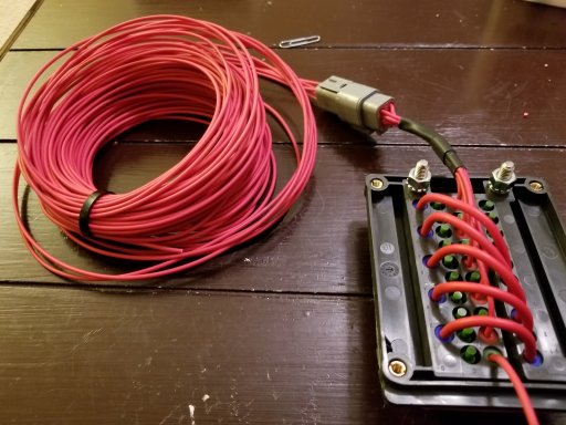
Radio Power Distribution (RIGrunner 4005H Powerpole connection box):
Constant Power (8 gauge + & - wires from passenger BS 6 fuse block) via Powerwerx ITS-12 Timer/Voltage Disconnect Switch Box (+ output post direct to RIGrunner, - output post to RIGrunner via inline fuse)
-Yaesu 400 XDR transceiver
-Powerwerx DB-750X transceiver
-(Cobra 75 CB radio relay power)
-Powerwerx Voltmeter/Temperature Meter monitor)
-(spare fan?)
[ITS-12 override switch with power from ITS-12 + input post]


Rear Power Switch Panel
0. Switch Lights
1. Cargo lights
2. Hatch lights
3. Tailgate lights
4. Air Compressor (relay trigger )
5. Water (relay trigger)
6. USB power outlet
7. USB Outlet Switch


Sent from my iPad using OB Talk
 
Last edited:

Dur66

Rank II
Launch Member

Contributor III

Good Morning,
I'm researching what solar system to get. I looked into that charge controller. It's made for lead-acid batteries. The only one ACO power makes for a AGM (absorbed glass mat) battery is 10 amps. I'm a subscriber to 4XOverland and Ronny Dahl on YouTube. They both did good videos explaining solar for overlanding. As a result of that, I think that rigid panels would not be good for my use. Panels which can be rolled up are. Lots of info to absorb.
Durwin
 

Texassailor

Rank III
Launch Member

Contributor III

684
Austin, TX
Member #

8476

Actually, ACOPOWER says that the 40A MPPT controller works with "sealed, gel, and flooded" batteries on page 1 of their instruction manual. AGM is considered "sealed" as far as I can tell. Regardless, I chose the USER profile in the configuration to precisely state the charging parameters for my specific 34R-PC1500T Odyssey Extreme batteries. The selectable parameters are shown on page 17 of the instruction manual. I referred to the Odyssey manual for my batteries to set these parameters (for which ACOPOWER's "sealed" configuration was a little too high).

Here is the manual: https://www.acopower.com/media/attachment/file/h/y/hy-mppt2-20-30-40-4.pdf

BTW, my solar panel is a foldable soft panel . . . not rigid. Weighs only 8 pounds . . . unlike those heavy glass panels. And, from many sites comparing products the ACOPOWER "monocrystalline photovoltaic panels are from SUNPOWER - the highest conversion efficiency module provider in the world, which increases conversion efficiency up to 25%." The max power voltage is 20.88V which can be fully utilized by an MPPT controller, not an PWM controller.
 
Last edited:

Texassailor

Rank III
Launch Member

Contributor III

684
Austin, TX
Member #

8476

I may also test out the Renology 160W flexible solar panel. It doesn't have the operating voltage or the efficiency of the ACOPOWER panel, but it does provide more watts. So, the 120W v 160W comparison will not be apples to apples . . . but, I'd like to see what the actual results would be in a direct comparison. The Renology panel has a bigger footprint and does not fold but is a bit lighter. Footprint is more important to me than weight (only a 2 lb. difference). The additional wattage is important but the lower operating voltage and efficiency of the Renology will mitigate this some.


NOTE: My SnoMaster fridge/freezer is a permanent fixture in my JKUR. It runs 24/7. I keep the freezer set at 5 degrees F and the fridge at 32 degrees F. The available temperate range of this unit is -8F to +50F.

Because of my office building, the Jeep isn't in the sun until about noon. After lunch, I place the ACOPOWER solar panel on my roof rack (it is so low profile no one knows it's there . . . so it is unlikely to be stolen). Solar panel works for about 5 hours until I take it down to go home. The batteries are fully charged (12.9V) by the time I go home. When not on the road for travel, I do plug my battery bank in at night using a "CTEK (56-674) Multi US 25000 8-step, Fully Automatic 12 Volt 25 Amp Battery Charger" This is a pricey unit ($250+ at Amazon) but really keeps my expensive Odyssey batteries in top condition.
 
Last edited:

Texassailor

Rank III
Launch Member

Contributor III

684
Austin, TX
Member #

8476

A couple of screen shots of the LCD display for the 40A MPPT controller:

In this image the solar panel's output is going primarily to recharging the battery. The load shown is a couple of small monitoring devices (including the MT50). You can see that the MPPT controller is taking in 14.7V and outputing 13.2V (nominally 12V). The input amperage is 6.1A (at the higher voltage) which translates into a combined 7.0A at the nominal 12V (battery plus load). With a PWM controller, the input from the solar panel would not be 14.7 volts, but a nominal 12V and the amperage form the panel would equal the amperage going to the battery and load. This is the benefit (from what I understand) of the MPPT controller over the PWM controller. When my solar panel voltages have been closer to the 18V+ end of the scale, the difference between Amps "IN" vs. Amps "OUT" is even higher.


Here is a screenshot when my fridge/freezer is running on HIGH:

The fridge accounts for about 4.6A of the load (0.1A for the MT50). The remaining amperage from solar panel is going to the battery . . . providing 3.0A.

My PWM controller would show something more like 5.9A at 13.0V from the solar panel with an output of 4.7A to the load and only 1.2A to the battery. I have never been able to squeeze out more than 6.0A (available to battery/load) from the PWM controller even with the sun at solar noon in a cloudless sky in June at latitude 30 degrees 16 minutes north.
 
Last edited:
  • Like
Reactions: Seppy

Dur66

Rank II
Launch Member

Contributor III

If you had it to do all over again, would you change anything? Thanks for posting all of this.
Durwin
 

Texassailor

Rank III
Launch Member

Contributor III

684
Austin, TX
Member #

8476

Size is the only issue . . . how much room all of this takes in the rear of my JKU. Would I change anything?
  • Fridge/freezer? No. I need 56 quarts and I LOVE the quality & performance of the SnoMaster.
  • Batteries? No. With the cage, they take up as little room as possible and I expect them to perform for years. I wish they offered a few more AHrs, but then they wouldn't fit in the engine compartment should I need to put one there in an emergency.
  • Solar panel(s)? Maybe. I haven't found a solar panel with the performance and form-factor of the ACOPOWER non-rigid foldable model. I think they make a 200W version that is in a kit. I would prefer a single 200W panel over two 120W panels. So, if I were doing it again, I'd start with the 40A MPPT controller (to allow for future expansion) and purchase a single ACOPOWER high efficienty 200W non-rigid foldable panel. Skip the kits with the included PWM controller (a waste of money UNLESS I need one in a pinch should my MPPT controller die unexpectedly).
  • All the other minor things like meters/shunts, breakers, battery selector/cutoff, fuse panels, etc.? Except for the BlueSea fuse panel, most of the other items were relatively inexpensive but high quality. Still, they take up room. I wouldn't trust burning my Jeep down to the ground, though, without some of these safety items like the breakers and fuse blocks.
  • The CTEC battery charger? No. I'd buy again in a heartbeat. Buy once, cry once. I'm hopeful this applies to this item and all the items above.
It has been painful paying for all of this stuff. Fortunately, I've spread most of it out over 6 months or so. Still, I'd hate to add it up and know what I actually spent. It is high quality gear and I don't expect to have to replace it anytime soon. Like I said above, I use this setup every day. I expect it will make my overlanding and camping more enjoyable; it already has. No more running out of ice or food floating in ice melt. The fridge/freezer keeps everything COLD.

I know that most people always rate what they have as the best. I'm usually pretty honest about what doesn't work for me. I consider this gear Cadillac quality. I could have spent much less (especially on the fridge and batteries). Of course, I would then expect to replace them more often. It is pay now or pay many times later. I was fortunate to have the money to spend on these luxuries. It wasn't too long ago that this would have to have remained a dream because I just couldn't afford it.

You started this thread by saying you were considering the Genesis Dual Battery setup. I think this could be a wise choice. This was my initial plan and I think you would be happy running everything off of that system (dual battery with a sPod type switching system). I chose to isolate my house batteries and solar. There is no wrong answer.
 
Last edited:

Dur66

Rank II
Launch Member

Contributor III

There is a lot of information to consider. Thank you. Whenever you get all of this mounted, I'm sure we would all like photos. Right off the top of my head, I'm thinking the controller could mount on one of the plastic panels in the rear cargo area or perhaps horizontally on top of a panel. Space is very limited in my two door. This would help towards being self-sufficient on the road.

Your system seems very well thought out.
Durwin
 

onbelay

Rank 0

Traveler I

My 2008 JKU setup, in addition to about 30 bonding/ground points to lower the noise floor. I left a few things out (e.g. some Deutsch connectors, my switches and switch panels, 13 pre-wired & terminated switch wires coiled behind the dash) but this should give you an idea. A few sample pics can be found at end of the post.

Regarding solar: we are adding the solar within the next few months. If you are considering solar, please consider the RFI generated by most MPPT controllers will cause issues with UHF/VHF/HF radios on certain frequencies. This is what lead me to a solar-quiet controller like the MorningStar (FCC Class B compliant). Also, the roof-mount flexible panels have been failing--in some cases catching fire (e.g. the *older* Renogy 100W panels the predate the recently-released panels--after 2-3 years. The jury is still out re: the ETFE covering, but I am skeptical. The best solar panel from a Watts per square foot ratio is the AM Solar SP 100, but note that it is a hard panel (at 1.38" it's also the thinnest available).

Everything in our solution is wired with SGX-rated wire or equivalent, crimp/solder/ adhesive lined heat shrink butt connectors, Techflex Insultherm, and additional adhesive lined heat shrink. I have a few Deutsch terminals throughout as well.

1. Passenger-side engine bay. Genesis Dual battery system, Pac-500 winch isolator, local and remote (+) and (-) circuits. Details below.

A. Genesis dual battery system with Odyssey PC1500 Group 34M batteries and Cole Hersee 200A smart isolator. Added a remote ground wire switch to override the smart isolator if desired.
B. PAC-500 solenoid on custom mount, welded to Genesis overbar, with remote ground wire switch to disconnect winch.
C. 2/0 SGX cable from dual battery common (-) alternator bracket.
D. Blue Sea 2151 dual MRBF terminal mount fuse block
E. 1/0 SGX cable, with 250A MRBF fuse, from from 1.D to a (+) DC bus in the driver-side engine bay.
F. 1/0 SGX cable, with 300A MRBF fuse from 1.D , through the firewall and into a (+) DC buss under passenger seat.
G. 1/0 SGX cable from dual battery common (-) to firewall ground stud.
H. 1/0 SGX cable from dual battery common (-) to fender ground stud.
I. ¾” Electric Motion EM 2080 braided strap from firewall ground stud to hood ground stud and to engine ground. This is an upgrade to existing, which fails after about 6 years.

2. Driver-side engine bay. ARB compressor, dual Cooper Bussman 15303 RTMR boxes, Blue Sea MRBF distribution, onboard battery charger

A. ARB CKMA 12 compressor with locker solenoids and remote 2 gallon ViAir tank.
B. Custom-built bracket to accommodate everything that follows:
C. Blue Sea 5196 three-post common source MRBF fuse block fed from 1.E above.
D. Two Cooper Bussman 15303 RTMR boxes
E. Noco Genius GenM2 dual-bank onboard battery charger. AC power from fender port, both DC (-) leads to bracket negative post, one (+) lead to a fused Cooper Bussman terminal , and one lead to the cranking battery’s (+) post.
F. 1/0 SGX ground cable from alternator bracket to dual battery common (-).
G. 1/0 SGX cable from alternator bracket to fender ground bolt.
H. Two 2AWG SGX cables, with 100A MRBF fuses, from the 5196 to the Cooper Bussman 15303s .
I. Two 1/0 SGX cables from custom built bracket to fender ground bolts.

3. Passenger footwell/underseat. AC/DC inverter, footwell lighting, DC distribution block, remote (+) circuit to rear Cooper Bussman 15303. Details below.

A. DC (+) three- post buss fed with 1/0 SGX cable from 1.E above
B. 800W inverter under passenger seat on JeepedJeep bracket. Soon to be replaced with 2000W pure sine inverter.
C. 1/0 SGX cable, from DC (+) buss to inverter
E. 1/0 SGX cable from inverter to chassis ground
F. 2AWG SGX cable from DC (+) bus to passenger rear cargo area Cooper Bussman 15303.
G. Footwell lighting tied into overhead lighting circuit.

4. Driver footwell/underseat. Two ham radios and a trailer brake controller fed from 2.D circuits above. Future automatic screwdriver antenna tuner.

A. Footwell lighting tied into overhead lighting circuit.

5. Passenger-side rear cargo area. Cooper Bussman 15303, Rigid D2 aux reverse lights, ARB 50 quart fridge/freezer, and future solar charge controller

A. Future Morningstar MPPT-40M solar charge controller connected to Cooper Bussman 15303 switched relay
B. Rigid D2 Aux reverse lights fed via 10AWG SGT cable from Cooper Bussman 15303. Relay is switched from 3-way cabin switch (on/off/on with reverse lights).

20180616_105229.jpg

20180628_110346.jpg

20180608_140106.jpg

IMG_20170818_212207214.jpg

Circuit6.jpg

Bussman7.jpg

DTM5.jpg 20180616_105229.jpg 20180628_110346.jpg 20180608_140106.jpg IMG_20170818_212207214.jpg Circuit6.jpg Bussman7.jpg

Rear.jpg

Front.jpg
 
Last edited:

onbelay

Rank 0

Traveler I

One more thing: CTEK devices are only rated to IP44. My entire setup is with marine grade components, and most devices are IP67 or greater. I would not put anything mission critical in my setup that was only splash resistant.