How can you wire a switch panel for accessories but have a rocker switch system as a back up?

  • HTML tutorial

Enthusiast I

404
Vacaville, CA, USA
First Name
Paul
Last Name
Breshears
Member #

30252

Hello, I am just starting to add some accessories to my rig. I installed onboard air, I will be adding a winch once my bumper is finished being made, and I have some pod lights to install. I really wanted to run a cheap switch panel like the Auxbeam 8 gang, but I want to have a set of rocker switches in my glove box as a back up in case the switch panel fails (especially since I am using a cheap brand, not something like a switch pro.) Can anyone link a thread explaining how I would go about doing this, or give me the basic idea of how I would wire that up here? Thanks a lot!
 

reaver

Rank VI
Member

Explorer I

3,680
Caldwell, ID, USA
First Name
Brian
Last Name
McGahuey
Member #

23711

Ham/GMRS Callsign
GMRS WRMV941
Well, there's not really an stupid easy way to do this.

The easiest way I can think of is to run two positive wires to the lights. One comes from the glove box switches, and the other comes from auxbeam relay box.

This **SHOULD** provide two independent power sources for the lights. Mind you, I've not tested this setup.

Auxbeam makes an 8 gang box that uses normal Relays and fuses. Much easier to troubleshoot than a solid state setup. Just food for thought, if you haven't purchased one yet.
 

OTH Overland

Local Expert Washington, USA
Member
Investor

Trail Blazer III

4,847
Camano Island, WA, USA
First Name
Dave
Last Name
Ballard
Member #

20527

Ham/GMRS Callsign
N7XQP
Service Branch
Fire/EMS/SAR
If you really want both options, the simplest way would be to wire both manual switch and auxbeam in parallel to the lights/devices then install a double throw switch or relay in the main power feed to both switch systems. This way you can select either manual or solid state as the control but not both at the same time. solid state electronics can be sensitive to backfeed if both sides were energized at the same time. another option is to use a junction block and leave the manual side disconnected until / if you need it, then manually switch it out. the solid state stuff is pretty reliable these days, have heard good things about the auxbeam stuff, ozark overland on you tube uses it in his rigs. I have switch pros in both my rigs one of them for several years and no issues.
 

Enthusiast I

404
Vacaville, CA, USA
First Name
Paul
Last Name
Breshears
Member #

30252

If you really want both options, the simplest way would be to wire both manual switch and auxbeam in parallel to the lights/devices then install a double throw switch or relay in the main power feed to both switch systems. This way you can select either manual or solid state as the control but not both at the same time. solid state electronics can be sensitive to backfeed if both sides were energized at the same time. another option is to use a junction block and leave the manual side disconnected until / if you need it, then manually switch it out. the solid state stuff is pretty reliable these days, have heard good things about the auxbeam stuff, ozark overland on you tube uses it in his rigs. I have switch pros in both my rigs one of them for several years and no issues.
That’s a good idea. The more I’m thinking about it, if the auxbeam were to fail it would be easy enough to remove and rewire my compressor or winch if I had to in the field. Maybe I’ll run solid state by itself and then to do a back up system if it ever fails. Thanks for the response!
 

reaver

Rank VI
Member

Explorer I

3,680
Caldwell, ID, USA
First Name
Brian
Last Name
McGahuey
Member #

23711

Ham/GMRS Callsign
GMRS WRMV941
That’s a good idea. The more I’m thinking about it, if the auxbeam were to fail it would be easy enough to remove and rewire my compressor or winch if I had to in the field. Maybe I’ll run solid state by itself and then to do a back up system if it ever fails. Thanks for the response!
I'm a big proponent of using DTP or DT plugs to make things easier to remove/troubleshoot if there's a problem. You could easily hook the compressor up using a dt plug, and make a pigtail that connects directly to the battery. That way, of the switch controller fails, you can quickly disconnect the compressor, and use the pigtail to connect it directly to the battery.

DT and DTP connectors are both dust and water proof. Just stick with the good ones though (Deutch or Jready).
 
  • Like
Reactions: OutdoorTxs

El-Dracho

Ambassador, Europe
Moderator
Member
Supporter
Investor

Inventor I

13,232
Lampertheim, Germany
First Name
Bjoern
Last Name
Eldracher
Member #

20111

Ham/GMRS Callsign
DO3BE
I have seen something similar on yachts years ago. CAN bus systems and for the essential things in addition a conventional wiring as backup in case of failure. Maybe take a look in that area how the solutions of the wiring look like?
 

Mtnmn99

Rank V
Launch Member

Advocate III

2,333
Chamberlain, SD, USA
First Name
paul
Last Name
piazza
Member #

26596

Hello, I am just starting to add some accessories to my rig. I installed onboard air, I will be adding a winch once my bumper is finished being made, and I have some pod lights to install. I really wanted to run a cheap switch panel like the Auxbeam 8 gang, but I want to have a set of rocker switches in my glove box as a back up in case the switch panel fails (especially since I am using a cheap brand, not something like a switch pro.) Can anyone link a thread explaining how I would go about doing this, or give me the basic idea of how I would wire that up here? Thanks a lot!

I did something similar with my back up lights. The lights ran off both an aux switch and the rear back up lights. I used a diod and a relay. You can do the same with a relay. I will try to find my diagram when I get home tonight.

In your case you would use the main switch and then the back up with work if the switch went out. Same wire set up as I used.
 

Uniquely Us Adventures

Rank VIII
Member

Pathfinder I

8,787
Sacramento, California, United States
First Name
Daniel
Last Name
Montelbetti
Member #

41721

Ham/GMRS Callsign
HAM - KN6TKY & GMRS - WRQT727
Service Branch
FIRE/EMS
You could always store some short pieces of wire and some connectors And wire it in the field direct if need be. You could run paddle connectors at all your connection points so that all you have to do is slide the paddle connector off/on and attach your back up wire that could be pre-wired with a paddle on one side and the ring on the other so all you have to do is put it on the screw and connect the Paddle and you’re done. Just a thought kind of making a quick and easy wire harness type set up. And it would be cheap
 

Boort

Rank V
Launch Member

Member III

2,779
Colorado
Member #

9314

I did something similar with my back up lights. The lights ran off both an aux switch and the rear back up lights. I used a diod and a relay. You can do the same with a relay. I will try to find my diagram when I get home tonight.

In your case you would use the main switch and then the back up with work if the switch went out. Same wire set up as I used.
If you are able to locate the schemitic that you used for this I'd like to see it. I'm looking to add Aux Backup lights to one of my rigs and want them to turn on either by switch or when in reverse.

Thanks
Boort
 

Mtnmn99

Rank V
Launch Member

Advocate III

2,333
Chamberlain, SD, USA
First Name
paul
Last Name
piazza
Member #

26596

If you are able to locate the schemitic that you used for this I'd like to see it. I'm looking to add Aux Backup lights to one of my rigs and want them to turn on either by switch or when in reverse.

Thanks
Boort
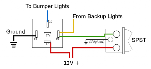
I am not home but did a quick search. I found the following image it is one way to wire it. I wired differently. I ran a relay between the yellow wire and the first relay, that way it did not back feed into the car electrical. I eventually removed the yellow wire relay and used a diode. The result was if the backup lights came on the bumper lights did the same, if the switch was on only the bumber lights lit.


1663183738573.png
 
  • Like
Reactions: Boort

OTH Overland

Local Expert Washington, USA
Member
Investor

Trail Blazer III

4,847
Camano Island, WA, USA
First Name
Dave
Last Name
Ballard
Member #

20527

Ham/GMRS Callsign
N7XQP
Service Branch
Fire/EMS/SAR
If you are able to locate the schemitic that you used for this I'd like to see it. I'm looking to add Aux Backup lights to one of my rigs and want them to turn on either by switch or when in reverse.

Thanks
Boort
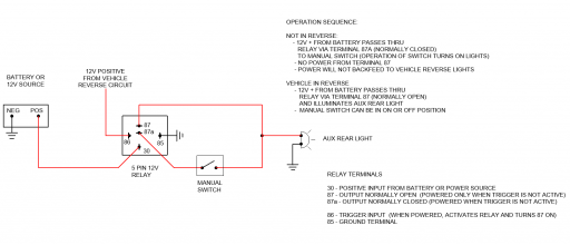
Here is one I did for a different project, I have modified it to apply to what you are looking to do. The relay will allow use of the rear lights manually and is not dependant on the relay being energized so will work with key off and defaults to manual control as long as the reverse switch is not active. the 12 volts from the bumper lights never mixes with the vehicle reverse lights so no chance of backfeed. The schematic posted above will power the lights, however it has the wires reversed on 87 and 30 and as such is feeding the relay backwards which is not critical if not connecting anything to 87a. as Paul mentions this method does require a second relay or a diode to be installed in the feed from the back up lights or they will be backfed while using the manual switch. not always a problem but can play heck with the CANBUS systems in newer vehicles.
1663186926612.png
 

Boort

Rank V
Launch Member

Member III

2,779
Colorado
Member #

9314

Here is one I did for a different project, I have modified it to apply to what you are looking to do. The relay will allow use of the rear lights manually and is not dependant on the relay being energized so will work with key off and defaults to manual control as long as the reverse switch is not active. the 12 volts from the bumper lights never mixes with the vehicle reverse lights so no chance of backfeed. The schematic posted above will power the lights, however it has the wires reversed on 87 and 30 and as such is feeding the relay backwards which is not critical if not connecting anything to 87a. as Paul mentions this method does require a second relay or a diode to be installed in the feed from the back up lights or they will be backfed while using the manual switch. not always a problem but can play heck with the CANBUS systems in newer vehicles.
View attachment 240632
I think this is what I was looking for. If I'm reading this correctly pin 87a is Normally Closed (NC) and the 87 is Normally Open (NO). In addition to the Diode in line before Pin 86, both 87/87a pins are on the the high current side so might be a good idea to put in another normally wired relay in place of the manual switch if the Aux lights pull a large load.

Boort
 

OTH Overland

Local Expert Washington, USA
Member
Investor

Trail Blazer III

4,847
Camano Island, WA, USA
First Name
Dave
Last Name
Ballard
Member #

20527

Ham/GMRS Callsign
N7XQP
Service Branch
Fire/EMS/SAR
I think this is what I was looking for. If I'm reading this correctly pin 87a is Normally Closed (NC) and the 87 is Normally Open (NO). In addition to the Diode in line before Pin 86, both 87/87a pins are on the the high current side so might be a good idea to put in another normally wired relay in place of the manual switch if the Aux lights pull a large load.

Boort
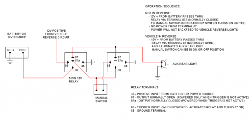
You should not need a diode on pin 86, pins 85 and 86 are simply two ends of a internal coil that when energized connects pin 30 to 87 when not energized pin 30 and 87a are connected instead. pin 85 is always low current draw and is isolated from the high amperage side. You are correct if you have a large amperage load connected through the manual switch you would want to put a relay in there or make sure the manual switch you use has a high enough amperage rating to operate the load directly. Todays led lighting uses a lot less amperage than the old stuff. wattage or amp draw should be on the light manufactures' information. If your switch is rated for more than 125% of the actual load you should be good to go. Schematic below includes a second relay to keep the high amp load from passing thru the manual switch. The 5 pin relays are available at any auto store or online, best way is to get them with a relay base, that way you can unplug and replace it if fails. I keep a couple of spares in my toolbox.
1663200785049.png
 
  • Like
Reactions: Ubiety and Boort

World Traveler III

1,518
Nokomis, FL, USA
First Name
John
Last Name
Fazio
Just my opinion, but I wouldn't install anything that I didn't have a high degree of confidence in (unless I was broken down and it was the only way out). If you are already wanting to have the back-up switches I would install those first then save up the coin and add the preferred pod later. It's possible the cheaper pod will never have a problem but planning for it's failure from the beginning is not recommended. This is a core principle in the Vehicle-Dependent Expedition Guide and some of the best advice we have used over the years.
 

Enthusiast I

404
Vacaville, CA, USA
First Name
Paul
Last Name
Breshears
Member #

30252

You should not need a diode on pin 86, pins 85 and 86 are simply two ends of a internal coil that when energized connects pin 30 to 87 when not energized pin 30 and 87a are connected instead. pin 85 is always low current draw and is isolated from the high amperage side. You are correct if you have a large amperage load connected through the manual switch you would want to put a relay in there or make sure the manual switch you use has a high enough amperage rating to operate the load directly. Todays led lighting uses a lot less amperage than the old stuff. wattage or amp draw should be on the light manufactures' information. If your switch is rated for more than 125% of the actual load you should be good to go. Schematic below includes a second relay to keep the high amp load from passing thru the manual switch. The 5 pin relays are available at any auto store or online, best way is to get them with a relay base, that way you can unplug and replace it if fails. I keep a couple of spares in my toolbox.
View attachment 240643
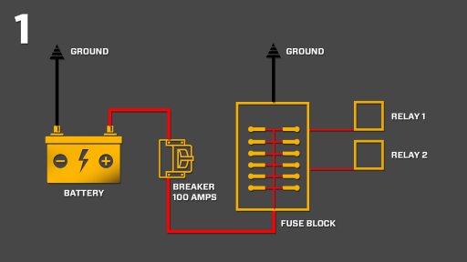
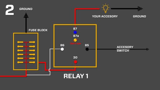
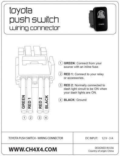
Hey guys, I am bringing this thread back to life. So I decided to use the Auxbeam 8 gang for all of my lights, etc. which I consider non essential, but I am doing the fused relay system for my air compressor and my winch. One, because those two things are essential in my opinion, and 2, because they loads are potentially more amps than the auxbeam is rated for. I successfully installed my winch, and wired in cab controls. I didn't have to put a relay, just an inline fuse, because I hooked up to the internal relay of the control box. Now I am am wanting to wire up and in cab switch for the air compressor. I want to use the negative switching featured by Michael on youtube. I have attached his wiring diagrams, and the wiring diagram for my switch. Since I am only doing one accessory, I will just skip the fuse block and use an inline fuse between the relay and battery. How would I wire the switch? Do I still need to give the switch 12v power from the battery, or only ignition tied 12v for the lights?

Thanks in advance!
 

Attachments

  • Like
Reactions: Boort