Creator III
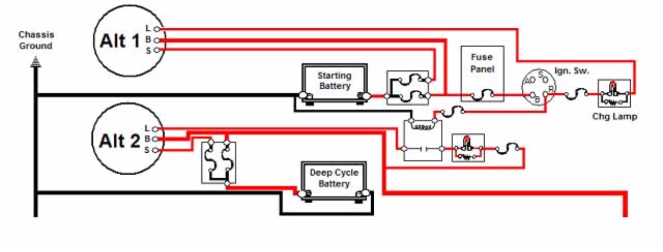
A mate of mine has fitted dual alternators.
Both alternators are identical (12v, 100amp).
In principal, one alternator charges the main battery and one charges the auxiliary battery.
But, he's also fitted a voltage sensing split charge between the two batteries.
He's wired the voltage sensing relay so the relay only energises when the auxiliary battery voltage rises above the activation threshold. Which wasn't what he intended (should have been the other way round), but, it works - or did for a while. One alternator has now stopped working - I suspect the voltage regulator has failed open circuit.
The debate we've been having is one of imbalance between the alternators.
For now, let's assume there is no resistance to each of the electrical connection.
My concern was that one alternator could end up back feeding the other, based on the batteries internal resistance and the fact that the alternators, while both the same, will not be absolutely identical in their outputs. i.e. the voltage maybe slightly different, and the current draw, depending on the state of each battery, could be different, even though the batteries will act as one accumulator.
Result - one alternator ends up try to drive the other as a motor, hence why the regulator has failed.
Thoughts ????