I'm updating this thread as I've learned a lot on how to do this. There are multiple ways to wire up your accessory fuse panel, and that all depends on how you want to power the relay, and if you want to be able to use accessories with the vehicle on, or off. Hopefully, this explanation and diagram will help people run through all of this.
The basics of how this all works is this: you have a switch that you turn on, that then triggers a magnet in a relay that allows power to connect from your relay to the accessory.
The power that is used to activate the magnet in the relay is substantially lower than having the switch connected directly to your accessory. It's a lot safer this way.
This should be used as a good general overview, and I hope the explanations are clear cut enough for everyone interested in DIY & wanting a system that you can fix yourself.
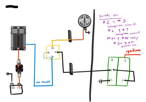
Config 1 / Positive Switching
This configuration powers the relay & the accessory via the 12v fuse panel.
This configuration is great because you'll only have 1 wire PER accessory going through the firewall, and it is a low power (green wire).
You can power accessories whenever you'd like, as long as you tap Pin 2 to a CONSTANT fuse.
If you tapped Pin 2 of the Switch to a SWITCHED FUSE (ONLY ON WHEN VEHICLE IS ON, LIKE RADIO).
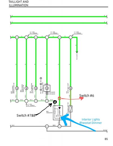
When the car is on and the dash lights are off & the switch is OFF, then the lower light will not be on. // Dash Lights also
When the car is on and the dash lights are on & the switch is OFF, then the lower light will be on.
When the car is on and the dash lights are off & the switch is ON, then the lower light will not be on & the upper light will be on.
When the car is on and the dash lights are on & the switch is ON, then the lower light will be on & the upper light will be on.
When the car is off, nothing works.
If you tapped Pin 2 of the Switch to a CONSTANT (ALWAYS ON, LIKE IGNITION).
Lower light is ALWAYS on & accessories can be used whenever you wish. There will be Power draw from vehicle when car is off. However, you can turn this off by turning off the circuit breaker.
When switch is on, Upper Light will turn on.
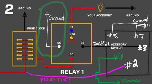
How does it work?
When the switch is OFF & the car is ON, pins 2 & 3 are not in contact with each other.
However, when the switch is ON & the car is ON, pin 2 connects to pin 3, and sends power to pin 86 on the relay.
The most important: Pin 86 with Pin 85 on the Relay activate the magnet that allows Pin 87 and Pin 30 to connect & send power to accessory.
The concept is similar to a gate.
When you flipped the switch from OFF to ON, Pin 2 came into contact with Pin 3, and then activated the Magnet in the Relay by supplying power to Pin 86.
Because Pin 86 has power, and Pin 85 is grounded already, Pin 30 can now send power to Pin 87.
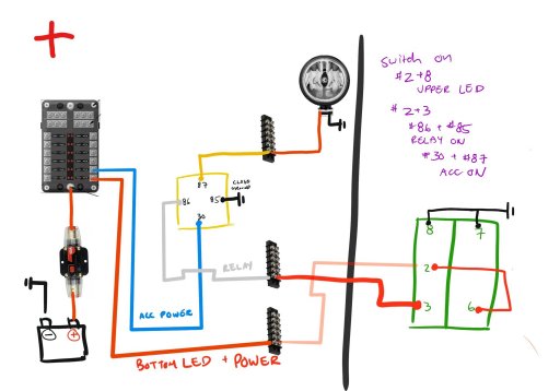
Config 2 / Negative Switching
This configuration is very similar to the one above, however, instead of a positive wire going through the firewall (green wire), you have a grounded wire going through the firewall.
You can turn on accessories whenever you'd like. In this setup, since Pin 86 is already powered, Pin 85 needs to be grounded.
This configuration is great because you'll only have 1 wire PER accessory going through the firewall & it is a ground wire, which is safer than sending positive wires through the firewall.
Explanation
The upper light is Pin 8 & 2, and the lower light is pin 7 & 6.
In the current setup, Pin 6 & 2 are grounded together locally in the Cab. When the switch is turned on, Pin 8 & 2 contact, allowing the upper light to turn on & for Pin 2 to complete the circuit with Pin 3.
Pin 2 touching Pin 3 is what finishes the circuit for the relay in the engine bay to activate. In essence, by allowing Pin 2 & 3 to contact, you've allowed Pin 86 and 85 to contact, and activate the magnet in the relay, which will allow power to pass from Pin 30 to Pin 87.
If you want the lower light to be turned on, then you need to connect Pin 7 to its own power source. It cannot be jumped with Pin 8.
Why? The lower light's circuit is connected regardless of if the switch is ON or OFF - all that matters is that the circuit is complete at Pin 7 & 6 via ground & power. So by having Pin 7 on it's own Positive 12v, and Pin 6 (which is already grounded by default with Pin 2), the lower light will be on. If you jump Pin 7 to 8 then the upper light will always be on with the lower light, as the lower light is always connected.
Lastly, you can opt to jump Pin 30 & 86 together, but this is only useful if your accessory is low AMPS.
Why? Because pin 30 is sending power THROUGH pin 87 to power your accessory & the common relay used in this application are rated for 40A. It's also better to just separate these things so you know what failed. Remember, Pin 86 is used to activate the relay with Pin 85. Pin 30 has all the power that will power up your accessory.
LAST THOUGHTS
This can all be done with 3 pin switches as well. They're actually more simple, as you're dealing with just 2 ground + 1 positive (for switch light), or 2 positive and 1 ground (for switch light).