

Trail Blazer III
- 6,000
- First Name
- Beau
- Last Name
- K12
- Member #
-
28559
- Service Branch
- Air Force
This mod has worked for my HQ19, and should also be similar for the other Black Series campers that have similar setups. I did forget to take pictures of some steps as I was doing them so it has some finished steps in there where stuff is already taped/sealed in place where they go. Overall the project was simple as long as you have knowledge of basic electrical. Biggest thing to note is to make sure that your wire gauge will work with what you want to do. Consult your codes to determine proper gauge wire to use.
I found from my research that working up the AC and outlets that are not on the inverter power cannot be easily jumped over to the inverter. So I needed to add a sub panel that is powered by the inverter.
For the install I used:
2 gang circuit breaker box
15A breaker (for GFCI outlets, can move the one from the original box if it is compatible with new one)
20A breaker (for AC unit, same as above if compatible with new box)
10 ft 12/2 romex with ground
3 ft 6/2 with ground cable, (capable of 50a load, there is 35A pull going to sub panel and 15a from current gfci outlets)
25ft. 8/2 with ground mc cable (this is a 40a rating to the sub panel that can pull a maximum of 35a)
2 Gang metal box with cover (for connecting wires)
Wire nuts
Electrical Tape
Multi-meter
Flat Head screw driver
Square-bit Screw driver
First step was to figure out where to setup the sub panel and wiring. For ease of running the wire from the current breaker box I decided to place it in the pass through right next to the main box.
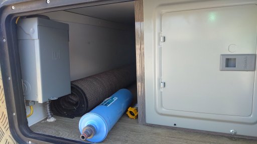
I decided on how to run the wires, With MC cable running the wires under the frame would be no problem as I do not have to worry about too much moisture. If the plastic loom is good enough for the already ran wires then MC cable will do perfectly well.
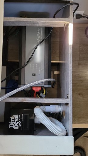
Next I drilled a hole next to the inverter to run the MC cable through. Outside diameter was .69” so I went with a .75 inch bit to give a little extra space. I will be filling in with silicone anyways so was not worried about air/water getting through.
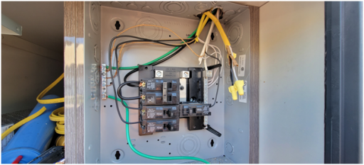
I ran the MC cable up through the hole and gave myself about 2 extra feet of cable to work with. Would much rather have extra cable than not enough and have to redo the wiring. I ran the cable along the other wires on the underside. This was very easy as there where pass through holes in the chassis struts that the MC cable fit through with ease, and gave attachment points for the zip ties to keep it in place. I ran it all the way to the pass through up front before drilling the hole to the sub panel. Again, I used a .75” bit to go through the flooring using silicone as a sealant. Once through I cut the metal housing of the MC cable to run up into the box, and unfortunately cut it a little to short so I had to use wire nuts to meet the circuit breakers (give yourself about a foot of wire inside the box to work with). Wiring is the same as a standard breaker panel, you will have your hot to the top of the breaker, neutral in the side panel and then ground to the box.
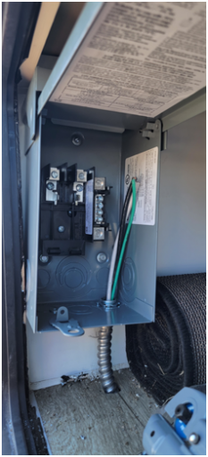
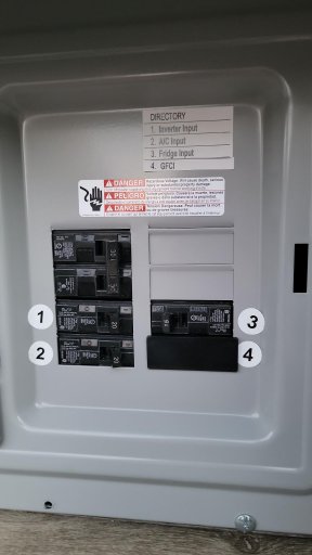
Next I opened the main panel and found the GFCI breaker (slot 4) and disconnected the romex attached to it as well as the neutral and ground wires. I used wire nuts and electrical tape to connect it to another 12/2 romex and ran it up and around the pass through to the sub panel (make sure that you tape the connections so that there is no exposed copper on any wire). I have not yet done the AC as the current inverter cannot handle the load, but to wire up the AC you would do the same process as the outlets. I have it all ready to go and only have to run 3 ft of romex to power the AC off the inverter. I made sure the breaker was in the “off” position while I finished the wiring.
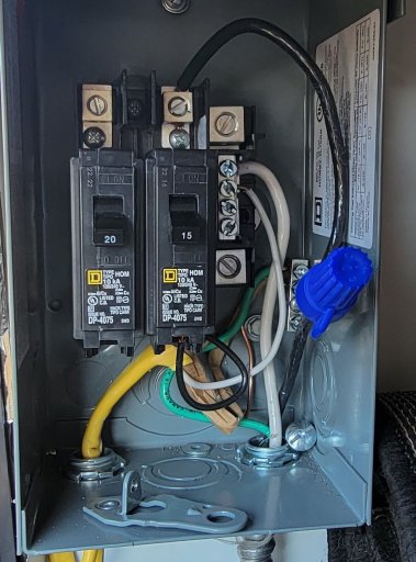
Once the romex is in the sub panel wire it up as a normal breaker, hot goes to bottom of the breaker, neutral to neutral and ground to the box.
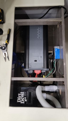
First part is to cut the circuit for the Inverter from the battery system by pressing the button on the top of the breaker in the battery compartment. For the standard inverter for the Black Series the back has a housing that is removable to expose the power in/out connections. The top is input, bottom is output. There are already 2 12/2 romex installed in the output for the current outlets inside the trailer that run off of inverter power.
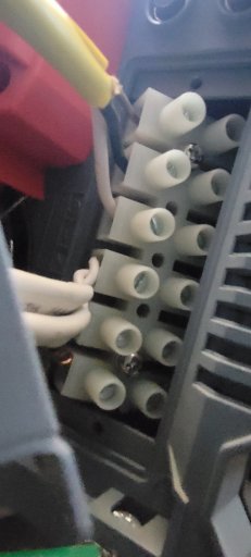
It is much easier to get the 6/2 with ground wire into the inverter when it is not connected to everything else. To do this remove the rear protector to expose the wire inputs. The 6/2 will go on the bottom three inputs. Unscrew the flat head screw on the outer portion of the housings, remove the other romex and insert the new romex through the cable pass through of the housing and then into the wire inputs. Tighten the screws to ensure that the wires to do jar loose or wiggle when you move them around. The terminals are rated at 6ga wires, but it was a pain to get them in for me and took some wiggling and luck to get them to fit properly. Until everything was tested I left the rear cover open so I did not have to open it again. Using the 2 gang box I ran the 2 romex removed from the inverter, MC cable and 6/2 wires into the box and used wire nuts to attached all wires to their corresponding wires. After attaching them with wire nuts and ensuring that all lines were separate from each other I turned the breaker for the inverter back on and started up the inverter. First task was to test the interior outlets that where already hooked up to the inverter and make sure they work with a multi-meter. Next I went to the sub panel and turned on the breaker for the other outlets. Tested those with a multi-meter and they worked as well. With everything tested and working I turned off the inverter and turned off the breaker again. I taped up all of my wire nut connections, and attached the top plate to the 2 gang box then closed up the inverter cover tightening up the wire pass through.
After tightening everything back up I went back through and re-tested everything to make sure that they work and nothing jarred loose.
I found from my research that working up the AC and outlets that are not on the inverter power cannot be easily jumped over to the inverter. So I needed to add a sub panel that is powered by the inverter.
For the install I used:
2 gang circuit breaker box
15A breaker (for GFCI outlets, can move the one from the original box if it is compatible with new one)
20A breaker (for AC unit, same as above if compatible with new box)
10 ft 12/2 romex with ground
3 ft 6/2 with ground cable, (capable of 50a load, there is 35A pull going to sub panel and 15a from current gfci outlets)
25ft. 8/2 with ground mc cable (this is a 40a rating to the sub panel that can pull a maximum of 35a)
2 Gang metal box with cover (for connecting wires)
Wire nuts
Electrical Tape
Multi-meter
Flat Head screw driver
Square-bit Screw driver
First step was to figure out where to setup the sub panel and wiring. For ease of running the wire from the current breaker box I decided to place it in the pass through right next to the main box.
I decided on how to run the wires, With MC cable running the wires under the frame would be no problem as I do not have to worry about too much moisture. If the plastic loom is good enough for the already ran wires then MC cable will do perfectly well.
Next I drilled a hole next to the inverter to run the MC cable through. Outside diameter was .69” so I went with a .75 inch bit to give a little extra space. I will be filling in with silicone anyways so was not worried about air/water getting through.
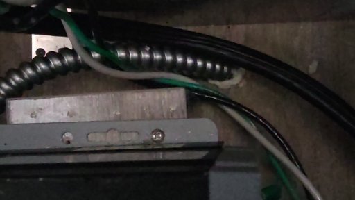
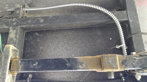
I ran the MC cable up through the hole and gave myself about 2 extra feet of cable to work with. Would much rather have extra cable than not enough and have to redo the wiring. I ran the cable along the other wires on the underside. This was very easy as there where pass through holes in the chassis struts that the MC cable fit through with ease, and gave attachment points for the zip ties to keep it in place. I ran it all the way to the pass through up front before drilling the hole to the sub panel. Again, I used a .75” bit to go through the flooring using silicone as a sealant. Once through I cut the metal housing of the MC cable to run up into the box, and unfortunately cut it a little to short so I had to use wire nuts to meet the circuit breakers (give yourself about a foot of wire inside the box to work with). Wiring is the same as a standard breaker panel, you will have your hot to the top of the breaker, neutral in the side panel and then ground to the box.
Next I opened the main panel and found the GFCI breaker (slot 4) and disconnected the romex attached to it as well as the neutral and ground wires. I used wire nuts and electrical tape to connect it to another 12/2 romex and ran it up and around the pass through to the sub panel (make sure that you tape the connections so that there is no exposed copper on any wire). I have not yet done the AC as the current inverter cannot handle the load, but to wire up the AC you would do the same process as the outlets. I have it all ready to go and only have to run 3 ft of romex to power the AC off the inverter. I made sure the breaker was in the “off” position while I finished the wiring.
Once the romex is in the sub panel wire it up as a normal breaker, hot goes to bottom of the breaker, neutral to neutral and ground to the box.
First part is to cut the circuit for the Inverter from the battery system by pressing the button on the top of the breaker in the battery compartment. For the standard inverter for the Black Series the back has a housing that is removable to expose the power in/out connections. The top is input, bottom is output. There are already 2 12/2 romex installed in the output for the current outlets inside the trailer that run off of inverter power.
It is much easier to get the 6/2 with ground wire into the inverter when it is not connected to everything else. To do this remove the rear protector to expose the wire inputs. The 6/2 will go on the bottom three inputs. Unscrew the flat head screw on the outer portion of the housings, remove the other romex and insert the new romex through the cable pass through of the housing and then into the wire inputs. Tighten the screws to ensure that the wires to do jar loose or wiggle when you move them around. The terminals are rated at 6ga wires, but it was a pain to get them in for me and took some wiggling and luck to get them to fit properly. Until everything was tested I left the rear cover open so I did not have to open it again. Using the 2 gang box I ran the 2 romex removed from the inverter, MC cable and 6/2 wires into the box and used wire nuts to attached all wires to their corresponding wires. After attaching them with wire nuts and ensuring that all lines were separate from each other I turned the breaker for the inverter back on and started up the inverter. First task was to test the interior outlets that where already hooked up to the inverter and make sure they work with a multi-meter. Next I went to the sub panel and turned on the breaker for the other outlets. Tested those with a multi-meter and they worked as well. With everything tested and working I turned off the inverter and turned off the breaker again. I taped up all of my wire nut connections, and attached the top plate to the 2 gang box then closed up the inverter cover tightening up the wire pass through.
After tightening everything back up I went back through and re-tested everything to make sure that they work and nothing jarred loose.