

Enthusiast III
Enthusiast III

Off-Road Ranger I
That is "Steel-It" polyurethane, using the spray where I can & the brush-on for the tricky bits. It's interesting stuff: Full of stainless steel flake, thick but flexible, weld thru, UV/fuel/oil/acid resistant, & conveniently hits in the second cool (form on top of function) department for meWhat paint are you using on the frame?


Off-Road Ranger I

Contributor III
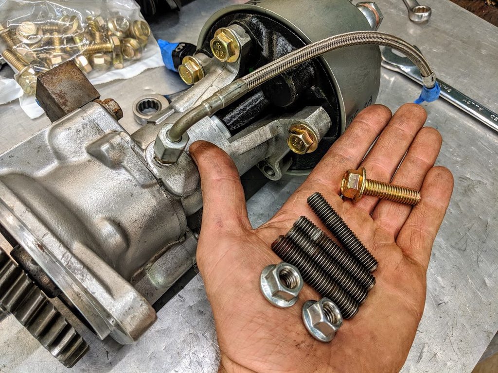
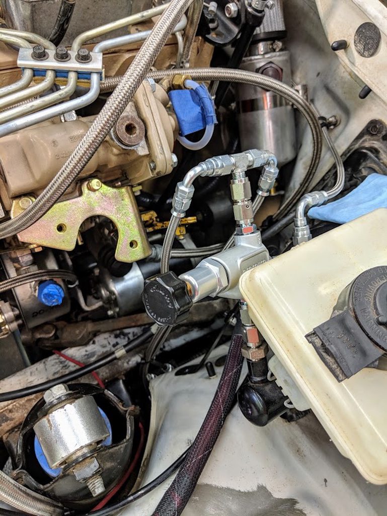
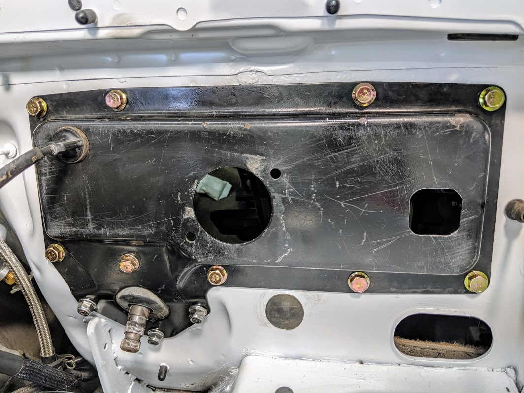
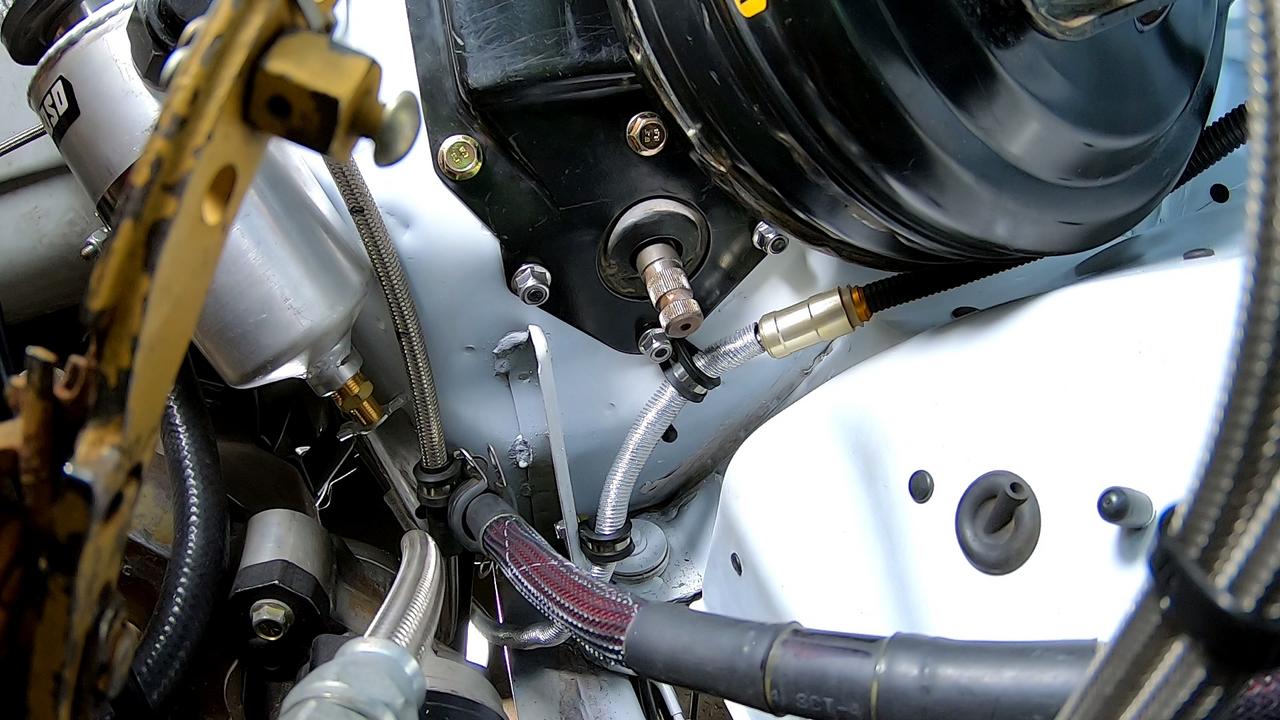
So you deleted the ABS Modulator all together? Fantastic! That thing is a pain in the butt. Brakes newb here: how do the brakes react without the ABS mod?I made some changes to my ABS delete setup. Those changes being the addition of a brake proportioning valve (thanks to some sound advice & not wanting to cut corners even if I'll be upgrading the brake calipers + rotors later in the build) & also ditched the aluminum swivel-unions for steel versions. I personally much prefer all the brake fittings be steel or stainless. The tee-fitting off the valve is roughly the same height as the master's reservoir, but AN fittings are typically fairly easy to bleed at the connection, so there shouldn't be too much to worry about causing a "bubble trap". If I had a lathe I would've taken some extra time to make adapters to save the need for those swivel-couplers that add length to the assembly, even though they are handy for installation/positioning:
Off-Road Ranger I
Yeah! Little block of problems be gone! In my experience they're usually a little more responsive & much easier to diagnose or bleed. And, at least with these older systems with terrible controllers, you don't have to deal with the sketchy failure modes. I borrowed a friends Silverado that was the same year & ABS generation as my Disco a few winters back (snow was getting a little too deep to daily the motorcycle) and when the ABS failed in a dry parking lot on that thing I nearly drove thru a building! It's far from uncommon for those older generation systems to fail like that.So you deleted the ABS Modulator all together? Fantastic! That thing is a pain in the butt. Brakes newb here: how do the brakes react without the ABS mod?
Contributor III
Fantastic! Well, fortunately, my shuttle is still remarkably functional (we'll see if that actually pans out with 600 extra lbs added to the drivetrain).Yeah! Little block of problems be gone! In my experience they're usually a little more responsive & much easier to diagnose or bleed. And, at least with these older systems with terrible controllers, you don't have to deal with the sketchy failure modes. I borrowed a friends Silverado that was the same year & ABS generation as my Disco a few winters back (snow was getting a little too deep to daily the motorcycle) and when the ABS failed in a dry parking lot on that thing I nearly drove thru a building! It's far from uncommon for those older generation systems to fail like that.
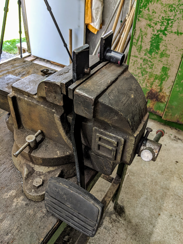
Finished the video on the ABS delete process for the Disco. After the fact I spotted a few places that could do with some spiral wrap protection, as well as a few more zipties. Also I had planned to build a little support bracket for the valve, but with these steel fittings I was impressed how rigid the whole assembly is! Oh & since I have a habit of spacing out on things when I get excited to drive a project again... I stuck a big piece of tape to the window saying "Bleed the Brakes!"
[VIDEO]
Off-Road Ranger I

Enthusiast III
Off-Road Ranger I
I'm hoping here within a few weeks, can hardly wait!When do you think you will be driving again?
Love your work btw.


Enthusiast III
Off-Road Ranger I


Off-Road Ranger I


Off-Road Ranger I


Off-Road Ranger I
This is an awesome build, friend. Love the mods. What all did you have to add to mount the cummings or was it fairly straight forward. I have a 1996 I'm looking to convert in many of the same ways you did. Bravo all the way around!Haven't done a build thread on a forum in a loooong time, but here goes. I'll try to catch up the project to the current state. Back in late 2014, after more than a year long search I spotted an unmodified low-mile 2002 Land Rover Discovery 2 a few states away. I'd often pondered about a grandiose plan to build myself a do-anything offroader + home on wheels. And it seemed I finally found a platform to set the idea in motion!
~ Build breakdown & plans below ~
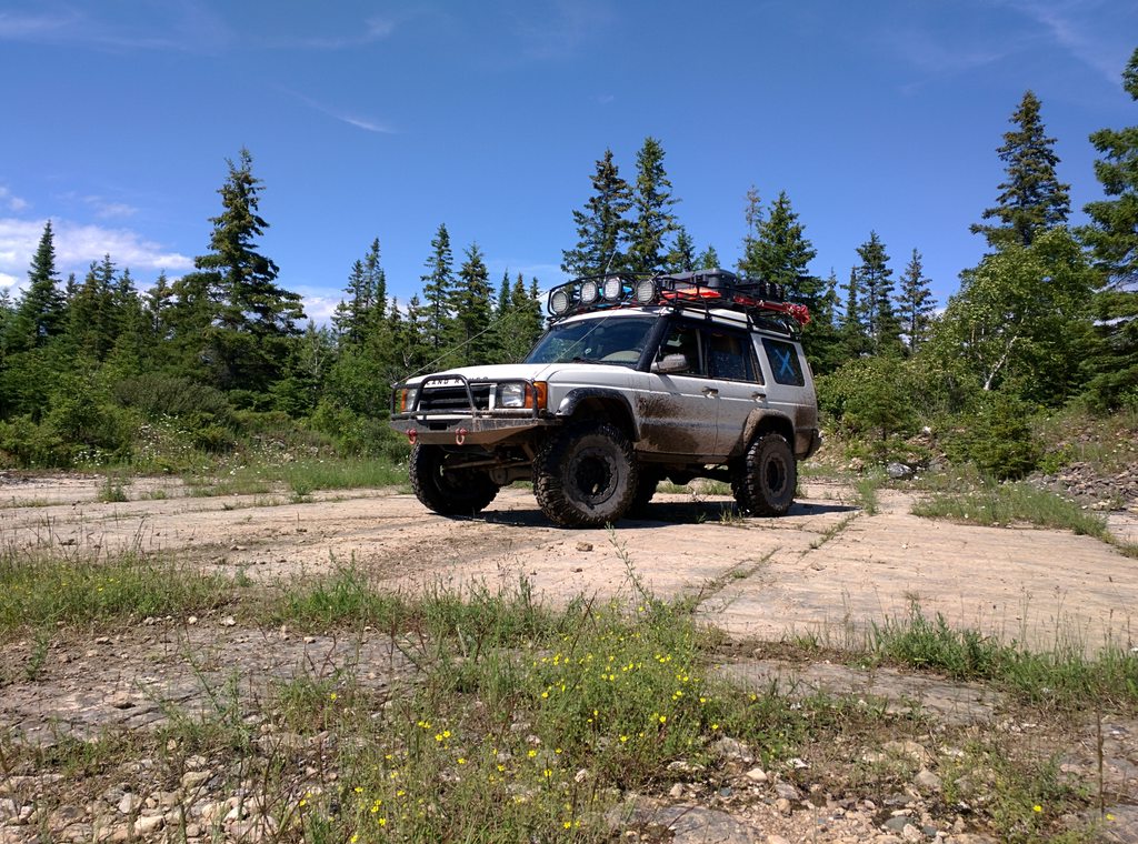
Here's a shot of it halfway built-up (lifted, camper, cargo, etc) bombing around the limestone plains of Drummond Island, over towards Canada, off the eastern shores of Michigan's Upper Peninsula:
And here in stock form, a clean slate to tear into just after dragging it home thru a monster snow storm out in Chicago:
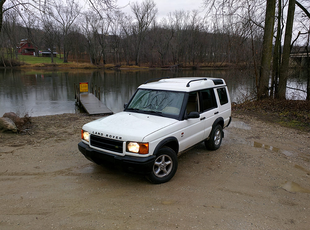
Now in a full fledged build-mode to receive a big powertrain swap to the tune of an upgraded turbo diesel Cummins engine, 5-speed transmission, & divorced transfer case:

UPGRADES:
Powerplant:
- Engine = Cummins 3.9L "mechanical" diesel 4-cylinder
- Mods = KDP fix, HD valve springs, 6BT oil filter plate & grid heater
- Boost = Super HX30W turbo on a cut 6BT manifold, stock injectors
- Injection = P-Pump with extra timing, ground fuel plate, 4k governor
- Fueling = Custom system, in-tank pump deleted, all stainless AN
Drivetrain:
- Transmission = Custom GM+Mopar NV4500 5-speed w/overdrive & big clutch set
- Transfer Case = Divorced all-wheel-drive Rover LT230 w/HD cross-pin & locking center diff
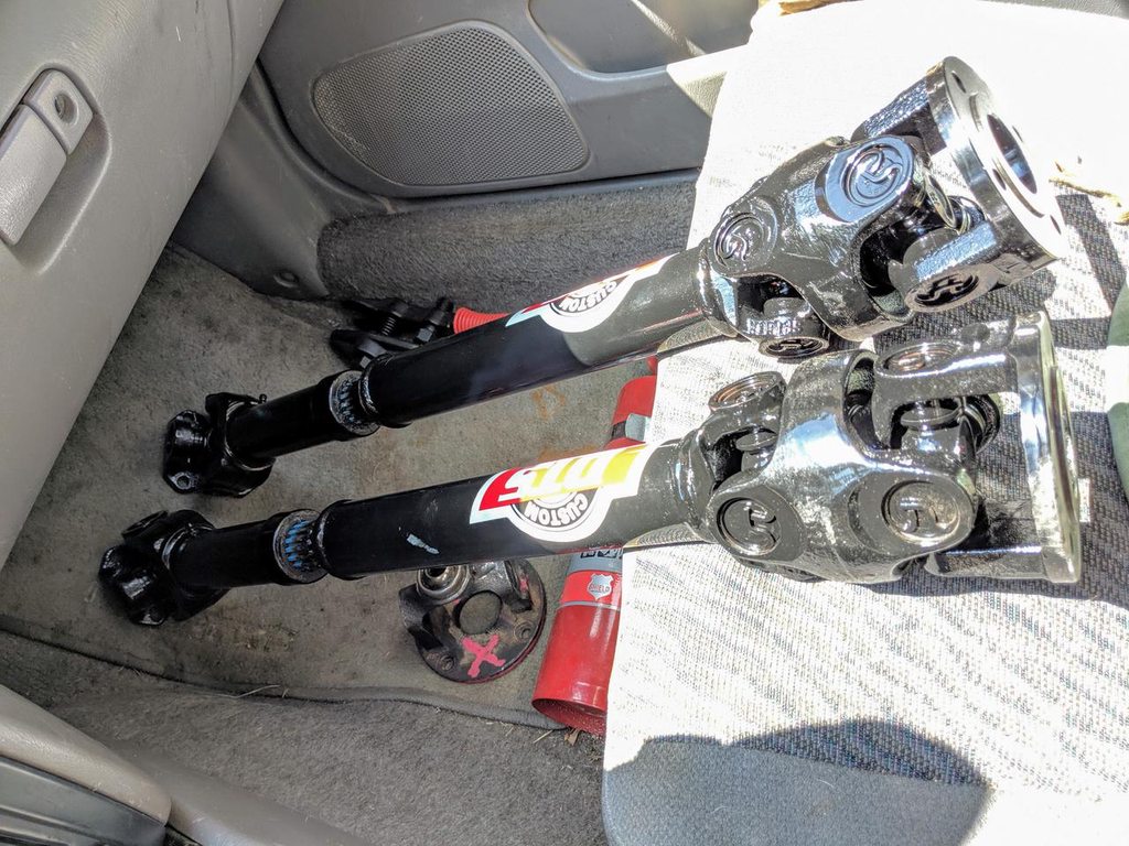
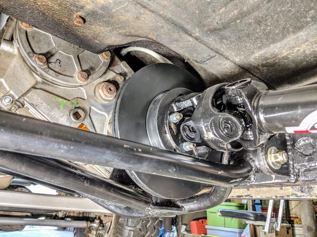
- Driveshafts = Custom length Tom Woods double-cardan long travel shafts
- Axles = Stock 1/2-ton Rover semi-floating 3rd-member solid axles
Suspension:
- Lift = Lucky8 4" suspension lift kit w/Terrafirma parts
- Wheels = Custom Trail Worthy Fab HMMWV double bead-locks
- Tires = Interco TrXus M/T in 35" tall x 12.5" wide
- Brakes = ABS delete w/ stainless steel AN hose
Exterior:
- Voyager full size roof-rack & rear hatch ladder
- Tactical Rovers front winch bumper
- 75mm Lucky8 Flexi fender flares
- Custom heavy duty hiem-joint & DOM tube steering links
- Land Cruiser FJ80 Steering Gear w/cooler & saginaw pump
- Custom "manual" Makrolon polycarbonate side windows
- Custom aluminum rear side-window access hatch
- Restored tubular steel tail-light guards
- Custom bush cables / limb risers
Electrics:
- Dual group34 Northstar batteries w/ manual override charging relay
- Full OEM electrical system delete & rewire (in process)
- Array of four 9" 225-watt LED high-mount offroad spot+flood lights
- Auxbeam LED headlight bulb upgrades
- CB radio with fiberglass antenna
Interior:
- Custom camper setup w/plentiful cabinet space & fold-out bed
- Wool insulation stuffed everywhere
- Custom window blackouts/insulation
- Saggy headliner stripped & coated with bedliner
PLANS:
~ Winch, or two of 'em!
~ Sliders: Custom build w/frame mounted legs + tree bars
~ Bumper: Tactical Rovers rear w/my own custom swing-out tire carrier
~ Axles: Ashcroft HD shafts, joints, & diffs ($$$$>) for the stock Rover axles, OR...
~ Axles: Build high-pinion full-floating Ford 9 axles ($$<) & dream about portals?
~ Lockers: Stuff whatever axles with both a True-Trac locker in front & Detroit out back
~ Tires: 37-39" so I can start utilizing more inexpensive military surplus bias-ply rubber
~ Steering: Custom mount a hydraulic assist-ram plumbed right into the steering gear
~ Suspension: My own planned custom 3-link front + 4-link rear, all DOM tube & heims
~ Springs: Up-rated to match loadout weight + bypass shocks w/king fox racerunner etc
~ Brakes: Custom mounted Range Rover Sport 6-pot & 4-pot non-float calipers w/stainless AN hoses
~ Tanks: For water & fuel, custom build to tuck between sliders & frame rails, both sides
~ Armor: Custom build skid 1/4" aluminum plates for trans+transfer case & fuel tank
~ Solar: Custom setup w/house battery mounted in the cabinets or undercarriage
~ Comms: Long range HAM + GMRS to extend the current CB radio setup
~ Seats: Mastercraft Sportsman pair up front only
~ Lighting: Exterior area/work
[ 11/30/17 edits: Updated most images to my imgur source ]
[ 6/30/18 edit: Added recent photo of the powertrain swap ]
[ 7/30/18 edit: Added build list & plans ]
[ 6/17/19 edit: Updated lists ]
cont...
⇝ Land Rover Disco 2 ~ Lifted, Camper, Cummins Diesel & 5speed ⇜
⇝ 4BT thread: (LINK) ~ Video of builds, travel, racing, etc: (LINK) ⇜
Off-Road Ranger I
Thanks! I have soooo many more mods in mind for this thing once it's back on the road. How I mounted the Cummins in there is a really long answer honestly... but all the details you could possibly want are here earlier in this thread & in the videos I have on the project.This is an awesome build, friend. Love the mods. What all did you have to add to mount the cummings or was it fairly straight forward. I have a 1996 I'm looking to convert in many of the same ways you did. Bravo all the way around!


Member II
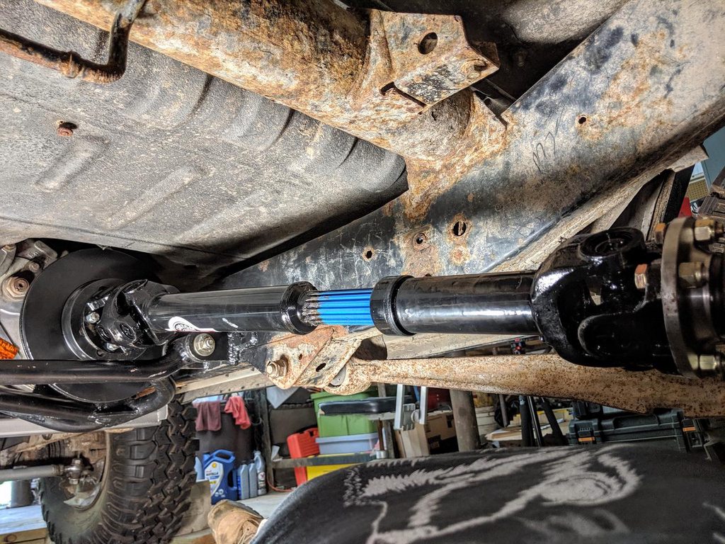
this scares me. there does not appear to be much spline left. am i seeing this right?

Member III
16986
It's in its extended position. Looks okay to me. A stock shaft is not built like this. I don't believe. This is an aftermarket shaft for higher than 3" lift LRD2's..this scares me. there does not appear to be much spline left. am i seeing this right?